


22
18-CD21D1-12
Installer’s Guide
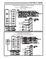
TABLE 14
Orifice
Twist Drill
Size If
Installed
At Sea
Level
ALTITUDE ABOVE SEA LEVEL
and Orifice Required At Other Elevations
2000 3000 4000 5000 6000 7000 8000 9000 10000
42
43
44
45
46
47
42
44
45
46
47
48
43
44
45
47
47
48
43
44
45
47
47
49
43
45
46
47
48
49
44
45
47
48
48
49
44
46
47
48
49
50
45
47
48
49
49
50
46
47
48
49
50
51
47
48
50
50
51
52
54
55
56
57
58
54
55
56
58
59
55
55
56
59
60
55
55
57
59
60
55
56
57
60
61
55
56
57
60
62
55
56
58
61
62
56
56
59
62
63
56
56
59
63
63
56
57
60
63
64
From National Fuel Gas Code - Table F-4
LIGHTING INSTRUCTIONS
▲
WARNING
!
DO NOT attempt to manually light the burner.
Failure to follow this warning could result in property
damage, personal injury or death.
Lighting instructions appear on each unit. Each
installation must be checked out at the time of
initial start up to insure proper operation of all
components. Check out should include putting
the unit through one complete cycle as outlined
below.
Turn on the main electrical supply and set the thermo-
stat above the indicated temperature. The ignitor will
automatically heat, then the gas valve is energized to
permit the flow of gas to the burners. After ignition
and flame is established, the flame control module
monitors the flame and supplies power to the gas valve
until the thermostat is satisfied.
TO SHUT OFF
For complete shutdown: Move the control switch on the
main gas valve to the “OFF” position (See Figures 25
and 26). Disconnect the electrical supply to the unit.
▲
CAUTION
!
If this is done during the cold weather months, provi-
sions must be taken to prevent freeze-up of all water
pipes and water receptacles.
Failure to follow this warning could result in property
damage.
Whenever your house is to be vacant, arrange
to have someone inspect your house for proper
temperature. This is very important in below
freezing weather. If for any reason your furnace
should fail to operate damage could result, such
as frozen water pipes.
White-Rodgers 36G gas valve
White-Rodgers 36J gas valve
Outlet Pressure Boss
Regulator
Adjustment
Inlet Pressure
Boss (opt.)
On/Off Switch
Outlet Pressure Boss
On/Off Switch
Inlet Pressure
Boss (opt.)
Regulator
Adjust
g
h
TABLE 13
GAS FLOW IN CUBIC FEET PER HOUR
2 CUBIC FOOT DIAL
SEC. FLOW SEC. FLOW SEC. FLOW SEC. FLOW
8
900
29
248
50
144
82
88
9
800
30
240
51
141
84
86
10
720
31
232
52
138
86
84
11
655
32
225
53
136
88
82
12
600
33
218
54
133
90
80
13
555
34
212
55
131
92
78
14
514
35
206
56
129
94
76
15
480
36
200
57
126
96
75
16
450
37
195
58
124
98
73
17
424
38
189
59
122
100
72
18
400
39
185
60
120
104
69
19
379
40
180
62
116
108
67
20
360
41
176
64
112
112
64
21
343
42
172
66
109
116
62
22
327
43
167
68
106
120
60
23
313
44
164
70
103
124
58
24
300
45
160
72
100
128
56
25
288
46
157
74
97
132
54
26
277
47
153
76
95
136
53
27
267
48
150
78
92
140
51
28
257
49
147
80
90
144
50


