background image

Removal and Installation

COM-SVN003B-EN

13 

Remove equalizer rubber plug and drain oil from 
replacement compressor.

Install replacement compressor in unit using slip 
couplings on suction and/or discharge tubing, as 
necessary.

Equalizer tubes that remain full diameter (1.125") 
between compressors can also be reassembled 
with slip couplings.

Equalizer tubes which reduce to 0.25" tubes should 
not be modified. If the 1.125" adapter tube is 
damaged during removal from the failed 
compressor, replace with new tube and cap.

Recharge oil to compressors as necessary to 
equally replace the oil amount that was removed.

a. Removal Instructions

Tip:

Before removing the existing tubing from the 
compressor, apply flux to the joint. This will aid in 
the flow of the braze material and help keep the 
joint clean for rebrazing. After fluxing, heat the joint 
evenly to slightly higher temperature than the 
melting temperature of the filler material. At this 
point, the two parts of the assembly should be 
easily separated.

b. Installation

c. Preparation:

i. For proper capillary action to occur, the tube and 

the fitting must be free of oil, grease, burrs, and 
oxide contamination. To remove the oil and 
grease a commercial solvent or denatured 
alcohol can be used. The surface may be 
properly cleaned by brushing with a stainless 
shell brush or by a stiff rubbing with emery cloth. 
Wipe the joint clean to remove small foreign 
particles such as emery dust, by wiping the 
surface with a clean cloth. Once the surfaces are 
clean, be careful not to touch them as oil from 
the skin will contaminate the surfaces.

ii. Pre-fit the existing tubing into the compressor to 

check that it has full insertion into the 
compressor fitting.

iii. Apply flux with a brush to the outside of the 

compressor connecting tubing, taking care to 
evenly apply the flux around the entire diameter. 
Care must also be taken not to get the flux inside 
of the tubing as this may result in contamination 
of the refrigerant system.

iv. Reinsert the tube into the compressor 

connection. If the tubing does not stay fully 
inserted, it must be restrained to prevent it from 
backing out of the compressor connection 
during the brazing process.

d. Brazing Technique

i. If possible, use a double-side torch while 

brazing.

ii. Use 40% silver brazing alloy with flux.

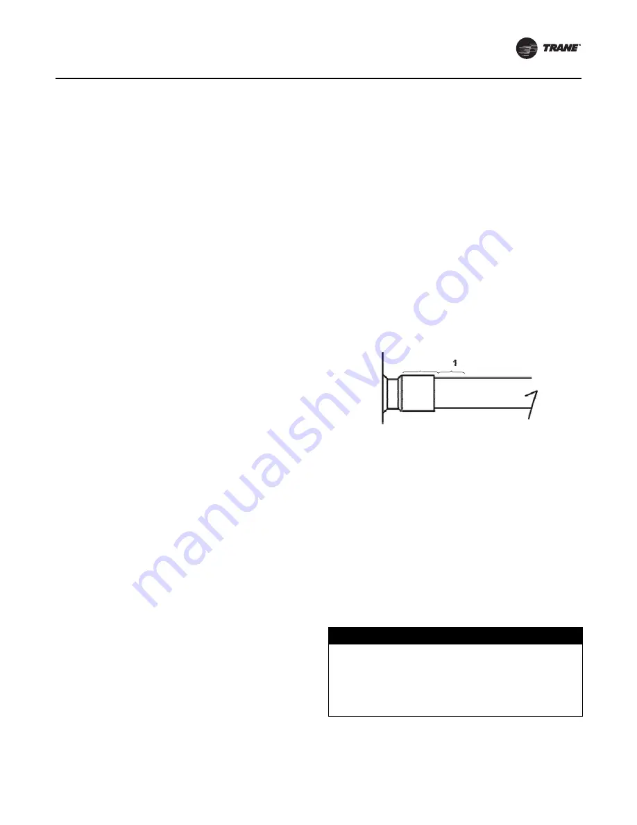
iii. Start heating the tube first. Evenly heat the tube, 

location 1 (see the figure below), until it reaches 
a dull red color. When using flux, this color is 
also a good indicator of when the proper brazing 
temperature has been reached. Continue 
heating the tube until the flux passes the 
“bubbling” temperature range and becomes 
quiet, completely fluid, and transparent—it 
should have the appearance of clear water.

iv. Direct the flame from the tube to the fitting, 

evenly heating it until the flux that may be 
remaining in the fitting is also completely fluid.

v. Sweep the torch between the fitting and the 

tube, locations 1 and 2 (see the figure below), 
with most of the heat being applied to the 
heavier and slower-heating fitting until the tube 
and fitting reach and maintain a uniform heat in 
both parts.

vi. Pull the flame slightly back and feed the brazing 

material in between the fitting and the tube. If the 
joint has been properly heated, the braze 
material should flow around and into the joint.

Important:

The heated base metal should melt the 
filler; the heat from the torch flame should 
not be what melts the filler.

vii.Once the braze material has flowed around and 

into the joint, briefly move the torch around the 
fitting to ensure complete capillary action into 
the joint.

viii.Check the joint to visually ensure that the braze 

material is completely around the joint.

e. Post-Braze

When brazing refrigerant connections, protect 
compressor body and terminal box from torch heat 
damage.

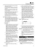
Figure 3. Brazing locations 1 and 2

NOTICE

Equipment Damage!

Flux is corrosive and could lead to long-term problems 
and equipment damage if not properly removed. If not 
cleaned off, flux could hide leaks. Quench the joint with 
water or a wet rag while the joint is still hot—but below 
900°F—to shock off the flux.


Содержание CSHW047

Страница 1: ...ing up and servicing of heating ventilating and air conditioning equipment can be hazardous and requires specific knowledge and training Improperly installed adjusted or altered equipment by an unqual...

Страница 2: ...hazardous situation which if not avoided could result in minor or moderate injury It could also be used to alert against unsafe practices NOTICE Indicates a situation that could result in equipment o...

Страница 3: ...hould only be mixed with dry nitrogen for pressurizing units Failure to follow these instructions could result in death or serious injury or equipment or property only damage WARNING Hazardous Service...

Страница 4: ...rmission Trane reserves the right to revise this publication at any time and to make changes to its content without obligation to notify any person of such revision or change Trademarks All trademarks...

Страница 5: ...8 Pre Installation Inspections 9 Repair Recommendations 9 Mechanical Failure 10 Electrical Failure 10 Two Types of Motor Failures 10 Removal and Installation 11 Removal 11 Compressor Replacement Tand...

Страница 6: ...1 step Unloading with solenoid not energized Digit 10 Design Sequence Factory Assigned Digit 11 Motor Protection Type 0 Internal Line Break Digit 12 Compressor Connections Variation 0 Standard Compres...

Страница 7: ...ion Some conditions will result in oil levels below the sight glass Off After several minutes theoil levels should be the same in each compressor and should be visible in the sightglass This is the be...

Страница 8: ...system charge exceeds 3 pounds per ton crankcase heaters are required If required heaters must be energized for a minimum of eight hours prior to starting the compressor to insure that liquid refrige...

Страница 9: ...ngs may not be of the same length Adjust as necessary for even unit lift Table 2 Compressor weight without oil charge Model Weight lb Weight kg CSHW 047 050 052 056 83 8 38 CSHW 052 2 86 39 CSHW 058 0...

Страница 10: ...rs using an acid test kit Use Trane Part Numbers CHM00414 and 45006 Two Types of Motor Failures Light If oil test kit is negative and oil is only slightly discolored treat in the same manner as a mech...

Страница 11: ...compressor Cut the refrigerant lines in a convenient location that allows reassembly with slip couplings Then unbraze the line from the compressor and reuse it when the replacement is installed WARNIN...

Страница 12: ...and shipping For single applications this equalizer port will need to be brazed shut with a 1 125 tube and cap If the replacement compressor requires a full oil charge then the compressor can be tipp...

Страница 13: ...of the refrigerant system iv Reinsert the tube into the compressor connection If the tubing does not stay fully inserted it must be restrained to prevent it from backing out of the compressor connecti...

Страница 14: ...order to protect themselves from potential electrical mechanical and chemical hazards MUST follow precautions in this manual and on the tags stickers and labels as well as the following instructions U...

Страница 15: ...equipment or property only damage Use only dry nitrogen with a pressure regulator for pressurizing unit Do not use acetylene oxygen or compressed air or mixtures containing them for pressure testing D...

Страница 16: ...ng the evaporator Verification Before Start Up Follow the instructions in the unit Installation Operation and Maintenance manual If there are no instructions available use these guidelines Before star...

Страница 17: ...ly when the compressor is operating Do not overcharge the unit Recommended system full load superheats unless specified differently in the unit Installation Operation and Maintenance manual is 16 F 20...

Страница 18: ...eat sub cooling oil sump superheat voltage and amperage Check all of the following on a regular basis System operating conditions System refrigerant charge level Oil levels and oil color Check electri...

Страница 19: ...mum of eight hours or it is defective Mechanical damage to the compressor has occurred Check compressor amperage It may also trip the compressor motor protection module or other unit electrical protec...

Страница 20: ...on Operation and Maintenance manual for possible diagnostics codes and corrective action Also check for Defective unit controls maximum 12 starts per hour Compressors cycling on safety controls Unit o...

Страница 21: ......

Страница 22: ......

Страница 23: ......

Страница 24: ...are committed to using environmentally conscious print practices Trane by Trane Technologies NYSE TT a global climate innovator creates comfortable energy efficient indoor environments for commercial...

Отзывы: