background image

MultiSat Control Panel Owner’s Manual

77

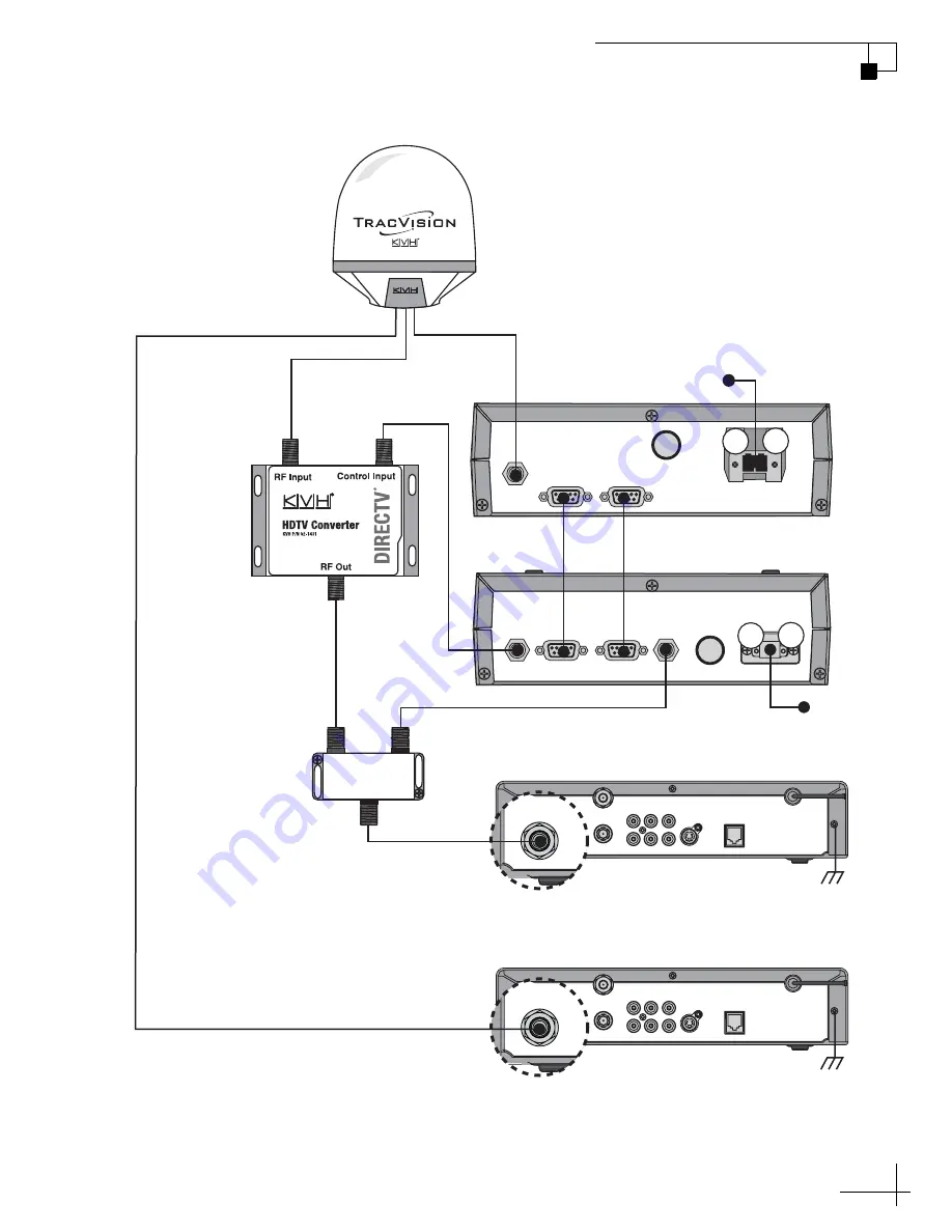
Appendix B - Wiring Diagrams

OUTPUT TO

ANTENNA

MAINTENANCE PORT

RF PORT

FUSE

POWER IN

MCU

+24 VDC

SATELLITE IN

OUT TO TV

TV ANT/CABLE IN

AUDIO

VIDEO

S-VIDEO

PHONE JACK

R

L

SATELLITE IN

HDTV

Converter

HDTV

CONTROL

ANTENNA UNIT 

RF PORT

TONE

DETECT

FUSE

POWER IN

+ / –

MCP

Secondary (Non-HD) Receiver - Optional

Primary (HD) Receiver 

(Controls satellite selection)

SATELLITE IN

OUT TO TV

TV ANT/CABLE IN

AUDIO

VIDEO

S-VIDEO

PHONE JACK

R

L

SATELLITE IN

RF1

RF2

Antenna

Splitter

+

+12 VDC

Data/Power

OUT

OUT

INPUT

+

Gnd to MCU

DC Return (-)

Gnd to MCU

DC Return (-)

Wiring 1 HD Receiver - M9 Configuration

Содержание Mobile Receiver

Страница 1: ...HDTV Converter Owner s Manual HDTV Converter for DIRECTV Service...

Страница 2: ...s Inc KVH and TracVision are registered trademarks of KVH Industries Inc DIRECTV is a registered trademark of DIRECTV Inc KU_HD_OM_CoverBW_3 07 HDTV Converter for DIRECTV Service flip here to view qui...

Страница 3: ...es Next Return Return to Get Antenna Status Sleep Mode On Off Set sleep on off Yes Next Return Update Frequency Data Sat frequency scan Yes Next Return Man control antenna Yes Next Return Adjust Azimu...

Страница 4: ...er NOTE The MultiSat Control Panel is not a standalone unit It is an add on accessory for an installed DVB compatible TracVision satellite TV antenna system Please direct questions comments or suggest...

Страница 5: ...ght colored dome with contrasting baseplate is a registered trademark of KVH Industries Inc DVB Digital Video Broadcasting is a registered trademark of the DVB Project DIRECTV is an official trademark...

Страница 6: ...t only 12 Wiring the MCP to the Antenna R4 R5 Switchplate 13 Wiring the MCP to the Antenna M5 M7 Switchplate 16 Wiring the MCP to the Antenna M5 M7 GyroTrac 19 Wiring the MCP to the Antenna M9 21 Wiri...

Страница 7: ...ing Latitude and Longitude 47 Changing the Sleep Mode Setting 48 Changing the Instant On Mode Setting 49 Restarting the Antenna 50 Viewing Antenna Status 51 Manually Controlling the Antenna 53 Updatin...

Страница 8: ...ation 72 Wiring 1 HD Receiver M5 M7 Switchplate Configuration 73 Wiring 2 or More HD Receivers M5 M7 Switchplate Configuration 74 Wiring 1 HD Receiver M5 M7 GyroTrac Configuration 75 Wiring 2 or More...

Страница 9: ...Panel Owner s Manual 1 Chapter 1 Introduction 1 Introduction This chapter provides a basic overview of this manual and your MultiSat Control Panel with HDTV converter Contents Using this Manual 3 Pro...

Страница 10: ...learn how to operate and set up the control panel The user or servicing technician should refer to the Troubleshooting chapter to help identify the cause of a system problem Notifications Used in thi...

Страница 11: ...Corresponding Button Related Documentation In addition to this Owner s Manual the following documents are provided with the product Text Example Description Text in brackets or the pound sign indicate...

Страница 12: ...s see Figure 1 2 Now you can easily configure the antenna select satellites check system status and restart the antenna right from the MCP Figure 1 2 MCP Front Panel The MCP connects to your TracVisio...

Страница 13: ...ner s Manual 6 Chapter 1 Introduction HDTV Converter The HDTV converter adjusts the signal frequency of DIRECTV s 110 satellite allowing the TracVision system to receive its high definition channels F...

Страница 14: ...e MCP to the Antenna M5 M7 Switchplate 16 Wiring the MCP to the Antenna M5 M7 GyroTrac 19 Wiring the MCP to the Antenna M9 21 Wiring the HDTV Converter and Receiver 23 Mounting the MCP 25 Selecting th...

Страница 15: ...ged in shipment 3 Gather all of the tools and materials listed below You will need these items to complete the installation Flat head and Phillips head screwdrivers 7 16 open end wrench Electric drill...

Страница 16: ...l the antenna Be sure to leave enough room at the MCP s rear panel for connecting the cables see Figure 2 2 for MCP dimensions Figure 2 2 MCP Dimensions Since the supplied main control cable and RF co...

Страница 17: ...al see page 79 mark and cut out a hole in the mounting surface to accommodate the flush mount bracket see Figure 2 3 Figure 2 3 MCP Mounting Holes Layout 2 Using the same template mark the locations f...

Страница 18: ...you plan to mount the MCP to a horizontal surface 1 Slide the bracket onto the MCP from behind and position the front edge of the bracket over the seam line between the front bezel and the chassis 2 S...

Страница 19: ...maintenance port to the back of the switchplate This allows you to later connect the main control cable to the back of the switchplate hidden from view However if you wish you may skip this step and...

Страница 20: ...ort assembly see Figure 2 6 Figure 2 6 Standard Maintenance Port Assembly 5 Attach the MCP ready maintenance port assembly to the switchplate using two 4 24 screws see Figure 2 7 These screws simply r...

Страница 21: ...the RJ22 jack on the switchplate to the RF Port jack on the MCP 3 Connect a set of power wires from the switchplate s power output terminals to the plastic power plug supplied in the kitpack see Figur...

Страница 22: ...aintenance port to the back of the switchplate This allows you to later connect the main control cable to the back of the switchplate hidden from view However if you wish you may skip this step and si...

Страница 23: ...Assembly 5 Wire the TracVision antenna s data cable to the terminal board on the new maintenance port assembly Be sure to match the wire colors body color stripe color with the terminal board label 6...

Страница 24: ...the RJ22 jack on the switchplate to the RF Port jack on the MCP 3 Connect a set of power wires from the switchplate s power output terminals to the plastic power plug supplied in the kitpack see Figur...

Страница 25: ...Connect the RF control cable 3 wires to DB9 female from terminals 58 59 and 60 on the ADCU to the RF Port jack on the MCP see Figure 2 15 CAUTION For your own safety disconnect vessel power and make...

Страница 26: ...tic power plug supplied in the kitpack see Figure 2 16 for cable specifications see Figure 2 1 on page 9 Figure 2 16 MCP Power Plug 4 Plug the MCP power plug into the Power In jack on the MCP Secure i...

Страница 27: ...ce Port jack on the MCU to the Antenna Unit jack on the MCP see Figure 2 17 Figure 2 17 MCP to MCU Wiring 2 Connect the RF control cable DB9 female to DB9 female from the RF Port jack on the MCU to th...

Страница 28: ...ower to the plastic power plug supplied in the kitpack see Figure 2 18 For power cable specifications see Figure 2 1 on page 9 Figure 2 18 MCP Power Plug 4 Plug the MCP power plug into the Power In ja...

Страница 29: ...ol Input jack on the HDTV converter see Figure 2 19 Figure 2 19 HDTV Converter and Receiver Wiring 2 Connect the RF1 cable from the antenna to the RF Input jack on the HDTV converter If you wish to co...

Страница 30: ...F Out jack on the HDTV converter to either of the Out jacks on the supplied splitter 4 Connect an RF coax cable from the Tone Detect jack on the MCP to the other Out jack on the splitter 5 Connect an...

Страница 31: ...MCP and the mounting surface using a mild detergent 2 Peel the backing from the two supplied Velcro fabric squares and stick them to the bottom of the MCP see Figure 2 20 Figure 2 20 Velcro Mounting t...

Страница 32: ...the MCP If it is not attached attach the bracket as explained in Attaching the MCP Flush Mount Bracket Flush Mount only on page 12 2 Insert the MCP and bracket assembly into the mounting hole and secu...

Страница 33: ...rack the three DIRECTV satellites refer to Selecting Satellites to Track DualSat on page 46 for details on installing a different pair of satellites 1 Ensure the antenna has a clear unobstructed view...

Страница 34: ...apter 2 Installation 4 At Install satellite press YES 5 At Trisat mode press YES 6 At USA or Europe press USA The MCP installs the TriSat group of satellites into the antenna 7 Follow the steps in the...

Страница 35: ...elect Automatic mode or press MANUAL to select Manual mode see Figure 2 23 Figure 2 23 Sat Select Mode Menus on MCP 2 If you selected Automatic mode at Select SAT 101 and select a satellite pair to tr...

Страница 36: ...atically switch between either 101 110 or 101 119 see Figure 2 24 Figure 2 24 Automatic Sat Select Mode In Manual mode the user presses a button on the MCP whenever he she wishes to switch satellites...

Страница 37: ...1 119 and 110 the receiver needs to be configured for an Oval 3 LNB dish antenna type Since each model of receiver is different refer to the receiver s manual for details on viewing and changing the d...

Страница 38: ...peration This chapter explains how to access the system menu and switch satellites using the buttons on the control panel Contents Downloading the Program Guide to the Receiver 35 Switching Satellites...

Страница 39: ...uide which lists channels available on every DIRECTV satellite A channel is selectable only if it is loaded in the Program Guide NOTE The receiver downloads the channel listings for the 101 satellite...

Страница 40: ...y on page 45 Automatic Switching With Automatic Sat Select mode enabled the antenna switches between a pair of satellites automatically as necessary when you change channels using the receiver s remot...

Страница 41: ...ect mode enabled you can manually select satellites using the MCP front panel buttons Simply press the button under the desired satellite shown on the display see Figure 3 2 Figure 3 2 Manually Switch...

Страница 42: ...trol NOTE The primary receiver which is connected to the splitter controls satellite selection All secondary receivers will only be able to receive channels carried on the satellite that is currently...

Страница 43: ...ss the center button see Figure 3 4 Figure 3 4 Accessing the Menu Once you have accessed the menu the functions of the three MCP buttons are determined by the text shown directly above them on the dis...

Страница 44: ...ng the antenna Contents Adjusting Display Brightness 43 Selecting Satellites to Track TriSat 44 Choosing a Sat Select Mode TriSat Only 45 Selecting Satellites to Track DualSat 46 Manually Entering Lat...

Страница 45: ...he brightness of the MCP display Figure 4 1 Setting Display Brightness Default Display Menu Operations Mode Yes Next Return Select Next until Operations Mode is displayed Get Antenna Status Yes Next R...

Страница 46: ...nsisting of the 101 110 and 119 satellites Figure 4 2 Selecting Satellites TriSat Default Display Menu Install Satellite Yes Next Return TriSat Mode Yes No Return USA or Europe USA Europe Return 101 1...

Страница 47: ...shown in Figure 4 3 to choose a Sat Select mode Automatic or Manual For details about these modes see Sat Select Modes on page 30 Figure 4 3 Choosing a Sat Select Mode Default Display Menu Set Sat Sel...

Страница 48: ...Satellites DualSat Default Display Menu Install Satellite Yes Next Return TriSat Mode Yes No Return Install A SAT Name Yes Next Cancel Select Next as required to display your choice for Satellite A th...

Страница 49: ...na Yes Next Return Man control antenna Yes Next Return Set Lat Long Yes Next Return Select Next until Operations mode is displayed Default Display Menu Install Satellite Yes Next Return Latitude N Ent...

Страница 50: ...power As soon as the vessel vehicle moves beyond a 1 2 window or the signal level changes significantly Sleep Mode automatically turns off and the system begins tracking the satellite again Figure 4 6...

Страница 51: ...e system was turned off and then the vessel vehicle moved after last acquiring the satellite via Instant On the antenna will undergo its standard initialization process This results in a brief delay F...

Страница 52: ...Menu Functions Restarting the Antenna Follow the process shown in Figure 4 8 to restart the antenna Figure 4 8 Restarting the Antenna Default Display Menu Restart Antenna Yes Next Return Select Next u...

Страница 53: ...ext Return Get Serial Number Yes Next Return Antenna Serial Get Version Yes Next Return Get Thres sig level Yes Next Return Get skew angle Yes Next Return Get bit error rate Yes Next Return CP Antenna...

Страница 54: ...versions Control Panel Antenna Main board RF board Get Serial Number Reports the antenna serial number Get Thres Sig Level Reports the currently received RF signal level and threshold minimum RF level...

Страница 55: ...e sure to select NO at the Make Antenna Track screen Figure 4 11 Manually Controlling the Antenna Operations Mode Yes Next Return Get Antenna Status Yes Next Return Man Control Antenna Yes Next Return...

Страница 56: ...ocess you will need to enter the symbol rate and FEC code You can find this satellite data on the web at www lyngsat com or www satcodx com neither website is affiliated with KVH To update the satelli...

Страница 57: ...trol Antenna Yes Next Return Control Antenna Yes Next Return Select Next until Operations Mode is displayed Default Display Menu Select Next until Sat Frequency Scan is displayed Sat frequency Scan Ye...

Страница 58: ...enu Select Next until Configure Satellite is displayed Configure Satellite Yes Next Return Configure Satellite Sat A Sat B Sat C Polarization Enter Configure frequency Yes Next Cancel Select as requir...

Страница 59: ...sion of the KVH Flash Update Wizard along with flashing instructions from the KVH Partner Portal Before beginning the software upgrade follow the process shown in Figure 4 14 to halt the antenna Figur...

Страница 60: ...l problems that might occur following an MCP installation along with their possible causes and solutions It also explains how to get technical support For antenna specific troubleshooting information...

Страница 61: ...ear on the TV Make sure the antenna is tracking the 101 satellite and wait for the Program Guide to load It might take 20 minutes to complete Is the selected channel carried on a different satellite I...

Страница 62: ...Therefore if you experience any operating problem or require technical assistance please call or visit your local authorized TracVision dealer or distributor You can find an authorized technician near...

Страница 63: ...cable 9 pin male to 9 pin male 25 ft 32 0716 25 RF control cable switchplate version 9 pin female to RJ22 25 ft 32 0811 RF control cable ADCU version 9 pin female to 3 wires 25 ft 32 0618 25 RF contr...

Страница 64: ...Owner s Manual 65 Appendix A Computer Diagnostics Appendix A Computer Diagnostics This appendix explains how to connect a laptop PC to the antenna system via the MCP Contents Connecting a Laptop PC to...

Страница 65: ...nel Figure A 1 Main Flash Port on MCP To connect your laptop PC to the main flash port use the supplied flash adapter cable DB9 female to stereo plug see Figure A 2 Figure A 2 Flash Adapter Cable TIP...

Страница 66: ...Receiver R4 R5 Configuration 71 Wiring 2 or More HD Receivers R4 R5 Configuration 72 Wiring 1 HD Receiver M5 M7 Switchplate Configuration 73 Wiring 2 or More HD Receivers M5 M7Switchplate Configuratio...

Страница 67: ...TV Converter 02 1431 HDTV CONTROL ANTENNA UNIT RF PORT TONE DETECT FUSE POWER IN MCP Secondary Non HD Receiver Optional Primary HD Receiver controls satellite selection SATELLITE IN OUT TO TV TV ANT C...

Страница 68: ...rter 02 1431 HDTV CONTROL ANTENNA UNIT RF PORT TONE DETECT FUSE POWER IN MCP HD Receiver 2 Primary HD Receiver 1 controls satellite selection SATELLITE IN OUT TO TV TV ANT CABLE IN AUDIO VIDEO S VIDEO...

Страница 69: ...IN HDTV Converter 02 1431 HDTV CONTROL ANTENNA UNIT RF PORT TONE DETECT FUSE POWER IN MCP Secondary Non HD Receiver Optional Primary HD Receiver controls satellite selection SATELLITE IN OUT TO TV TV...

Страница 70: ...NE JACK R L SATELLITE IN HDTV Converter 02 1431 HDTV CONTROL ANTENNA UNIT RF PORT TONE DETECT FUSE POWER IN MCP HD Receiver 2 Primary HD Receiver 1 controls satellite selection SATELLITE IN OUT TO TV...

Страница 71: ...F PORT TONE DETECT FUSE POWER IN MCP SATELLITE IN OUT TO TV TV ANT CABLE IN AUDIO VIDEO S VIDEO PHONE JACK R L SATELLITE IN HDTV Converter 02 1431 Secondary Non HD Receiver Optional Primary HD Receive...

Страница 72: ...ultiswitch Additional HD or Standard Receivers 13 14 23 22 21 20 19 18 24 17 16 15 1 2 11 10 9 8 7 6 12 5 4 3 Green Label 48 47 38 39 40 41 42 43 37 44 45 46 60 59 50 51 52 53 54 55 49 56 57 58 Red La...

Страница 73: ...R L SATELLITE IN HDTV Converter HDTV CONTROL ANTENNA UNIT RF PORT TONE DETECT FUSE POWER IN MCP Secondary Non HD Receiver Optional Primary HD Receiver Controls satellite selection SATELLITE IN OUT TO...

Страница 74: ...IN MCP HD Receiver 2 Primary HD Receiver 1 controls satellite selection SATELLITE IN OUT TO TV TV ANT CABLE IN AUDIO VIDEO S VIDEO PHONE JACK R L SATELLITE IN RF2 RF1 Antenna Splitter 12 VDC LHCP 18V...

Страница 75: ...79 8 87 225 mm 7 62 194 mm 63 16 mm 3 08 78 mm 1 83 46 mm 63 16 mm 4x 136 3 45 mm 4x R 63 16 mm MCP Flush Mounting Template...

Страница 76: ...of KVH Industries Inc KVH Industries Inc 50 Enterprise Center Middletown RI 02842 5279 U S A Phone 1 401 847 3327 Fax 1 401 849 0045 E mail info kvh com KVH Europe A S Kokkedal Industripark 2B 2980 K...

Отзывы: