


© 2013 Tractel Ltd. All Rights Reserved.
4
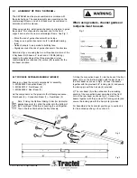
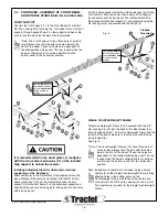
GENERAL WARNING
Read this general warning first.
In suspended platform operations, safety is a matter of life or death for riggers,
operators and by-standers. This warning is your share of duties for achieving safety.
YOUR DUTY TO UNDERSTAND AND COMPLY
.
1. It is the responsibility of the riggers and operators, and their
employer’s responsibility, if they operate under an
employer’s control, to strictly conform to the following
warnings.
2. It is imperative for safety and efficiency of operations
that this manual be
read and fully understood
by the
rigger and the operator before rigging or operating the
platform.
All instructions contained herein must be
carefully and strictly followed, including applicable SAIA
code of safe practices.
3. Should you hand over a skybeam under any conditions, to
any party operating out of your control, you must attach a
clean copy of this manual and draw to other party’s attention
that strictly following all the instructions therein is a matter of
life or death.
4. Before using the skybeam, the rigger and the operator must
become aware of all the requirements of federal, state,
provincial and local safety regulations not only applicable to
the skybeam, but also to the entire suspended scaffold
system or any component of it.
5. Never use the skybeam for any job other than lifting
personnel on suspended scaffold according to the
instructions of this manual.
6. Never load the skybeam above its rated load.
YOUR DUTY TO INSPECT AND MAINTAIN.
7. Keep this manual available at all times for easy reference
whenever required. Extra copies are available through the
equipment supplier.
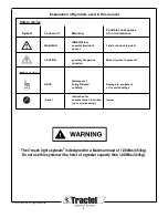
8. Carefully take notice of all the labels and markings affixed to
the skybeam. Never rig or operate the skybeam if any label,
normally fixed on it, is obscured or missing. Replacement
labels are available through the equipment supplier.
9. Every time the skybeam is to be rigged or used, check that
the skybeam, platform, hoists, wire ropes and other
components of the suspended scaffold system are complete
and in good working condition, prior to proceeding.
10. A careful and regular inspection of the platform hoists, wire
ropes and other components of the installation is part of the
safety requirements. If you have a question, call the
equipment supplier.
11. Before rigging, re-rigging and after, the skybeam must be
inspected by a Competent Person familiar with the skybeam
and professionally trained for the purpose.
12. Inspection by persons authorized by Griphoist is to be
carried out once every six months, to spot check the
condition of the beam and its components and that
rigging is being done correctly. A signed and dated
report card should be maintained for these purposes.
13. The manufacturer declines any responsibility for
consequences of repairs or modifications brought out of
its control to the product, specially by replacement of
original parts or repairs by another manufacturer.
YOUR DUTY TO TRAIN AND CONTROL PEOPLE.
Compliance with safety rules extends to rigging
operations which must be carried out only after securing
safe conditions of operation as per safety regulations and
requirements.
14. An operator must not be assigned to a suspended job or
to rigging for a suspended job, or to de-rigging after the
job, if that person is not:
a) mentally and physically fit for the purpose, especially
at heights.
b) competent for the job to be performed.
c) familiar with the scaffold equipment as rigged.
d) professionally trained for working under the above
requirements.
Except for the operations described in this manual, the
maintenance of the skybeam, as well as repairs, must be
exclusively done by repairers authorized by Griphoist.
Spare parts used for all equipment must be in
accordance with the product, no substitutions are
allowed.
15. Never let the skybeam or other components of a
suspended scaffold system be managed or operated by
any person other than authorized and assigned to the
job. Keep the equipment, either rigged or unrigged, out of
reach of unauthorized persons, while out of operation.
16. Training operators and riggers includes setting up rescue
procedure should a scaffold be brought to a standstill
during a job. Such procedure must be set up by a
Competent Person or its technical consultant, according
to the working conditions, prior to putting the equipment
into operation.
17. Every suspended job must be placed under the control of
a person having the required competence and authority
for checking that all the instructions prescribed by this
manual be regularly and efficiently carried out.
Draft #2 June 19, 2013