


© 2012 Tractel Ltd. All Rights Reserved.
17
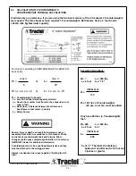
4.4
CONTINUED - ASSEMBLY OF ROOF BEAM
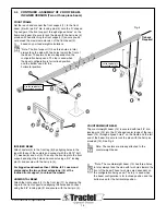
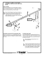
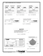
Level the outrigger beam and support assembly. Attach the
thimble end of the suspension wire rope to beam using a 5/8",
3-1/4 ton shackle (1). See Fig 10. Once the rope is attached,
set the assembly into working position. For beams with casters,
apply the brakes on all of the casters. Once in position install
taut tieback to the rear shackle (Fig. 13) as shown on Page 16
& 17 Fig. 14 & 15.
Note: The optional sliding collar shown in Fig. 10 is
for suspension only in the horizontal position. It is
not recommended for the inclined suspension beam.
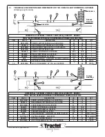
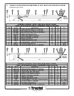
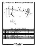
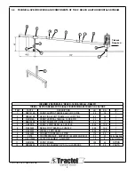
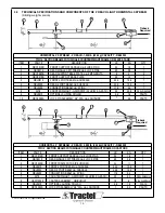
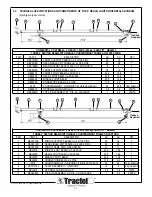
If you are using the two beam version of the 4’
skybeam 28 counterweights are required. The three
beam version requires 16 counterweights. Both
beams have a 4’ reach and a 1,000lb. (454 kg)
maximum capacity.
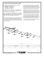
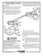
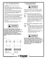
Add the counterweights (#3348) (up to 32 max.) to the
counterweight beam (See fig 8). Check once again the
maximum admissible load (see Section 4.4 page 17 –
Calculation of counterweight) related to the reach and the
number of counterweights on the counterweight beam. Install all
required counterweights on the counterweight beam by lowering
them over the extension pole, starting with the two inside poles.
Distribute the weight as equally as possible on each side of the
frame. See Fig.12.
When all weights are in place install the locking pin to prevent
removal. See Fig. 13.
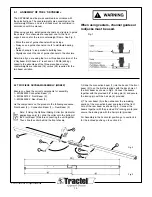
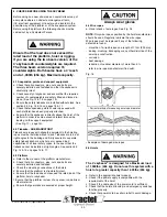
Attach the tieback wire rope at the back of the rear beam,
to the rear shackle inside. Always insure the tieback has
equivalent strength to the hoisting rope and they must be
installed without slack. See Fig 13. See Section 4.4 Fig. 11
& 12 for proper tie back instructions.
1
Primary wire rope is attached
here (see details below)
Beam Shackle
5/8” Shackle
Tieback Line
Wire Rope Thimble
Primary Wire Rope
Optional
sliding collar
Locking Pin
Rear shackle and
safety tieback as
required
Insert weights over the post,
starting on the inside and
evenly distributing from side
to side.
Fig. 10
Fig. 11
Fig. 12
Fig. 13