Tractel Griphoist Skybeam Скачать руководство пользователя страница 2

© 2013 Tractel Ltd. All Rights Reserved.

2

CONTENTS

PAGE

1. GENERAL WARNING

4

2. TRANSPORT AND HANDLING

5

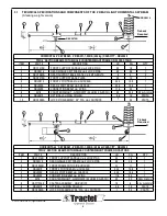
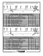
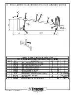
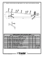
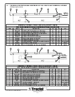
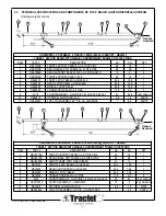
3. TECHNICAL SPECIFICATIONS OF THE 4’ SKYBEAM

6-9

3.1

Horizontal Version

3.2

Inclined Version

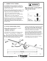
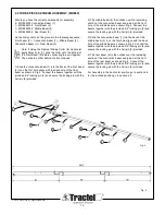
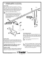
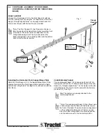
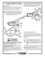
4. ASSEMBLY INSTRUCTIONS OF THE 4’ SKYBEAM

9-15

5. ASSEMBLY INSTRUCTIONS OTHER

16-19

5.1

Installation of Tieback

5.2 

Calculation of Counterweights skybeams (reference)

5.3 

Set up of Primary Wire Ropes

5.4

Set up of Outriggers and Counterweights

6. CHECKS BEFORE USING THE SKYBEAM

20

6.1

Suspension Points and Support Equipment

6.2

Tieback

6.3

Platforms

6.4

Wire Ropes

6.5

Hoists

7. USE AND OPERATION OF THE SKYBEAM

21

8. INFORMATION FOR MAINTENANCE

21

9. SKYBEAM LABELS AND MARKINGS

22-23

4’ reach light skybeam

® 

1,000 lb. (454kg) capacity

temporary outrigger beam for suspended platforms

assembly and operating instructions

Содержание Griphoist Skybeam

Страница 1: ...ngeles 1 800 675 6727 griphoist usa tractel com Canada Montreal 1 800 561 3229 Toronto 1 800 561 3229 griphoist canada tractel com temporary outrigger beam for suspended platforms assembly manual for Tractel Griphoist Division 4 Horizontal Beam 4 Inclined Beam Tieback Required Tieback Required Tieback Required Tieback Required ...

Страница 2: ...k 5 2 Calculation of Counterweights skybeams reference 5 3 Set up of Primary Wire Ropes 5 4 Set up of Outriggers and Counterweights 6 CHECKS BEFORE USING THE SKYBEAM 20 6 1 Suspension Points and Support Equipment 6 2 Tieback 6 3 Platforms 6 4 Wire Ropes 6 5 Hoists 7 USE AND OPERATION OF THE SKYBEAM 21 8 INFORMATION FOR MAINTENANCE 21 9 SKYBEAM LABELS AND MARKINGS 22 23 4 reach light skybeam 1 000 ...

Страница 3: ...bly dangerous Minor injuries to persons situation Other Advice Statement of NOTE Policy Related Damage to equipment to Safety or its surroundings Instruction for none documentation in writing none i e record keeping 2013 Tractel Ltd All Rights Reserved 3 The 4 reach light skybeam is designed for a Maximum load of 1 000lbs 454kg Do not use this system with a hoist of a greater capacity then 1 000lb...

Страница 4: ...f the installation is part of the safety requirements If you have a question call the equipment supplier 11 Before rigging re rigging and after the skybeam must be inspected by a Competent Person familiar with the skybeam and professionally trained for the purpose 12 Inspection by persons authorized by Griphoist is to be carried out once every six months to spot check the condition of the beam and...

Страница 5: ...giving a safe access to the operator in compliance with safety regulations b another suspension wire rope has been safely rigged to the suspension platform 27 Never operate a platform and its accessories especially electric ones in a potentially explosive atmosphere 28 For any job to be performed on the suspended equipment consider and control the specific risks related to the nature of the job 29...

Страница 6: ...910 OPTIONAL SLIDING COLLAR 3 6 1 6 PARTS 10 RBC3080A LOCK PIN ASSEMBLY 3 4 DIA c w LANYARDS 1 0 5 PARTS HORIZONTAL 4 SKYBEAM 4 REACH 1 000lb 454 kg CAPACITY RBL0040 TWO 4 SECTION BEAMS WITH SINGLE COUNTERWEIGHT FRAME ON CASTORS ITEM PART DESCRIPTION LB KG QTY 1 RBC1010B FRONT SUPPORT SADDLE c w 3 LOCK PINS 35 16 1 2 RBC2010 REAR SINGLE CWT FRAME c w 2 LOCK PINS 60 28 1 3 RBH1050B FRONT FRAME WITH...

Страница 7: ...ights Reserved 7 3 1 TECHNICAL SPECIFICATIONS AND COMPONENTS OF THE 4 REACH LIGHT HORIZONTAL SKYBEAM HORIZONTAL 4 SKYBEAM 4 REACH 1 000lb 454 kg CAPACITY RBL0041 THREE 4 SECTION BEAMS WITH SINGLE COUNTERWEIGHT FRAME ON CASTORS ITEM PART DESCRIPTION LB KG QTY 1 RBC1010B FRONT SUPPORT SADDLE c w 3 LOCK PINS 35 16 1 2 RBC2010B REAR SINGLE CWT FRAME c w 2 LOCK PINS 60 28 1 3 RBH1050B FRONT FRAME WITH ...

Страница 8: ...AR SINGLE CWT FRAME c w 2 LOCK PINS 60 28 1 3 RBI1016A FRONT VERTICAL TUBE c w 1 LOCK PIN 22 10 1 4 RBH1050B FRONT FRAME WITH SIDE HOLDER 24 11 1 5 RBL0210 FRONT 4 FOOT BEAM c w SHACKLE 34 4 15 6 1 6 RBL0230 REAR 4 FOOT BEAM c w SHACKLE 34 9 15 9 1 7 RBL0200 CONNECTION BEAM c w 2 PINS 11 9 5 4 1 8 3378 COUNTERWEIGHT GRIPHOIST 55 LB 25 KG EACH 55 25 28 by Griphoist 9 HAC17W99 CASTER ASSEMBLY GRIPHO...

Страница 9: ... 28 1 3 RBI1016A FRONT VERTICAL TUBE c w 1 LOCK PIN 22 10 1 4 RBH1050B FRONT FRAME WITH SIDE HOLDER 24 11 1 5 RBL0210 FRONT 4 FOOT BEAM c w SHACKLE 34 4 15 6 1 6 RBL0230 REAR 4 FOOT BEAM c w SHACKLE 34 9 15 9 1 7 RBL0220 MIDDLE 4 FOOT BEAM 32 2 14 6 1 8 RBL0200 CONNECTION BEAM c w 2 PINS 11 9 5 4 2 9 3378 COUNTERWEIGHT GRIPHOIST 55 LB 25 KG EACH 55 25 16 by Griphoist 10 HAC17W99 CASTER ASSEMBLY GR...

Страница 10: ...st 9 RBL0910 OPTIONAL SLIDING COLLAR 3 6 1 6 PARTS 10 RBC3080A LOCK PIN ASSEMBLY 3 4 DIA c w LANYARDS 1 0 5 PARTS HORIZONTAL 4 SKYBEAM 4 REACH 1 000lb 454 kg CAPACITY RBL0020 TWO 4 SECTION BEAMS WITH SINGLE COUNTERWEIGHT FRAME ON CASTORS ITEM PART DESCRIPTION LB KG QTY 1 RBC1010B FRONT SUPPORT SADDLE c w 3 LOCK PINS 35 16 1 2 RBC2010 REAR SINGLE CWT FRAME c w 2 LOCK PINS 60 28 1 3 RBH1050B FRONT F...

Страница 11: ...w LANYARDS 1 0 5 PARTS 3 3 TECHNICAL SPECIFICATIONS AND COMPONENTS OF THE 4 REACH LIGHT HORIZONTAL SKYBEAM HORIZONTAL 4 SKYBEAM 4 REACH 1 000lb 454 kg CAPACITY RBL0021 THREE 4 SECTION BEAMS WITH SINGLE COUNTERWEIGHT FRAME ON CASTORS ITEM PART DESCRIPTION LB KG QTY 1 RBC1010B FRONT SUPPORT SADDLE c w 3 LOCK PINS 35 16 1 2 RBC2010B REAR SINGLE CWT FRAME c w 2 LOCK PINS 60 28 1 3 RBH1050B FRONT FRAME...

Страница 12: ...ly 1 MRBL0200 Connection Beam 1 1 MRBL0210 4 Front Beam 2 1 MRBL0230 4 Rear Beam 3 Lie the components on the ground in the following sequence Front beam 2 Connection Beam 1 Rear Beam 3 Note If Using the Optional Sliding Collar for Horizontal applications only 4 slide the collar onto the bottom of the Front Beam 2 before connecting the unit together Then slide the collar behind the front shackle 20...

Страница 13: ...ir pin 6 provided 2013 Tractel Ltd All Rights Reserved 13 2 The middle beam 3 then slides over the remaining section of the connection beam and joined at the front hole of the middle beam as shown Fig 4 Connect the beams together with the provided 3 4 locking pin 5 and secure the locking pin with the hair pin 6 provided 3 Slide the connection beam 1 into the back of the middle beam 3 to so the fir...

Страница 14: ... a 3 4 locking pin 3 and secure with the hair pin 4 For bigger loads reaches than 1000lbs 5 Ft use wood plates under the two vertical extensions 10 of the inclined front support to unload the wheels HORIZONTAL BEAM Attach the front support 1 to the front leg 11 by slipping the Leg into the front support and aligning the holes and connect using the 3 4 locking pin 3 and secure with the hair pin 4 C...

Страница 15: ... the leg into the Front Support and aligning the holes and connect using the 3 4 Locking Pin 3 and secure with the Hair Pin 4 2012 Tractel Ltd All Rights Reserved 15 COUNTERWEIGHT BEAM The counterweight beam 12 is secured with two 3 4 dia locking pins 13 into the U shaped center ledge of the rear beam 14 through aligned holes on the frame and the tail end of the beam Be sure to lock the pins with ...

Страница 16: ...d with two 3 4 dia Locking Pins 3 into the back of the Rear Beam 14 through aligned holes on the Counterweight Frame and the tail end of the beam Be sure to lock the pins with the hair pins provided 4 See Fig 8 Note The Counterweight Frames 13 have three sets of holes in total Always face the side with two holes toward the front of the beam These two holes are dependent on the configuration being ...

Страница 17: ...8 Check once again the maximum admissible load see Section 4 4 page 17 Calculation of counterweight related to the reach and the number of counterweights on the counterweight beam Install all required counterweights on the counterweight beam by lowering them over the extension pole starting with the two inside poles Distribute the weight as equally as possible on each side of the frame See Fig 12 ...

Страница 18: ...sting ropes and must be installed without slack NOTE 1 Tieback may also be installed from the tip of the roof beam 2 When using the two tiebacks one must be on each side of the beam 2013 Tractel Ltd All Rights Reserved 18 TWO TIEBACKS ARE REQUIRED IF BETWEEN 25 TO 50 OF CENTERLINE ONE MUST BE ON EACH SIDE OF THE CENTERLINE SKYBEAM SKYBEAM ONE TIEBACK IS REQUIRED WITHIN 25 OF THE CENTERLINE TIEBACK...

Страница 19: ...ed without slack NOTE 1 Tieback may also be installed from the tip of the roof beam 2 When using the two tiebacks one must be on each side of the beam Secondary wire rope tieback Note only one required within 25 Two are required if between 25 and 50 of the beam Tiebacks are not permitted beyond 50 TIEBACK REQUIRED TIEBACKS NOT ALLOWED IN THIS AREA TIEBACKS NOT ALLOWED IN THIS AREA TWO TIEBACKS ARE...

Страница 20: ...ation Counterweights must be a nonflowable material and they must be attached to the outrigger beam Always use tieback wire ropes capable of holding the full load 2013 Tractel Ltd All Rights Reserved 20 5 2 CALCULATION OF COUNTERWEIGHTS COUNTERWEIGHT FORMULA CALCULATIONS Provided only as a reference If you are using the two beam version of the 4 Skybeam 28 counterweights are required The three bea...

Страница 21: ...e required The three beam version requires 16 counterweights Both beams have a 4 reach and a 1 000lb 454 kg Maximum capacity 2013 Tractel Ltd All Rights Reserved 21 5 3 SET UP OF PRIMARY WIRE ROPES a Use only wire ropes as specified by the hoist manufacturer b Before setting up the wire ropes ensure that the suspension points are capable of supporting the hoist platform and its rated load with the...

Страница 22: ...nd firmly secured to separate safety tieback anchors which meet or exceed load capabilities of all local safety codes In the event that the tieback cannot be installed at right angles See section 5 0 Fig 14 15 on pages 16 17 6 3 Platform a Refer to the manual of the platform manufacturer b Check that all connectors pins nuts and bolts are securely installed and fastened c Check the mounting connec...

Страница 23: ...an electrician to check the power supply Never operate the platform if lifting is through the down button Keep the platform level To level the platform back its horizontal position only operate one of the two hoists Take a first aid kit radio and fire extinguisher for emergency Never stand on the railing Set the platform down on a safe support and remove tension from wire rope before moving the sk...

Страница 24: ...g 20 Part SPLB144A Fig 21 Part SPLB145A Fig 22 Part SPLB147A Fig 23 Part SPLB148A Fig 24 Part SPLB149A Fig 25 Part SPLB146A Fig 26 Part 7112A0119 2013 Tractel Ltd All Rights Reserved 24 9 0 LABELS AND MARKINGS FOR 4 SKYBEAMS ...

Страница 25: ... 2013 Tractel Ltd All Rights Reserved 25 9 1 CONTINUED LABELS AND MARKINGS FOR SKYBEAMS TIEBACK REQUIRED ...

Страница 26: ... 2013 Tractel Ltd All Rights Reserved 26 NOTES ...

Страница 27: ... 2013 Tractel Ltd All Rights Reserved 27 NOTES ...

Страница 28: ...ovement of our products the TRACTEL GROUP reserves the right to modify the specifications of the equipment described in this manual As a result illustrations may not represent exactly the product you receive components and or design may differ The companies of the TRACTEL GROUP and their agents or distributors will supply on request descriptive documentation on the full range of TRACTEL products l...

Отзывы: