
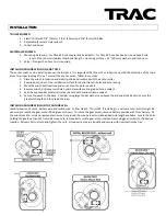

INSTALLING THE SWITCH PANEL
This winch includes a second switch and connector cable. Determine the location of the second switch (usually at the helm). Hold
the switch in the desired location and mark the center hole location and drill a 7/8” (22mm) hole for the connector to pass through.
Pass the switch connector through the hole and lay the switch flat on the installation surface. Align to switch, mark four screw holes,
remove switch. Drill the four marked screw holes with 1/8” (3mm) drill bit. Route the connector cable between winch and second
switch location. Install switch with four self-tapping screws provided. Excess cable can be coiled and tied off with plastic cable ties.
THE CIRCUIT BREAKER
This winch includes over-current circuit protection to protect the winch from overload. An additional 150-amp circuit breaker or
fuse is recommended to protect the battery wire between the winch and battery. Position for the fuse or breaker close to the
battery.
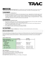
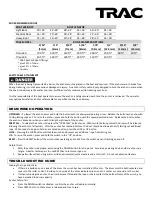
WIRING SELECTION & SPECIFICATION
Using incorrect wire can result in overloading and a fire. Using incorrect circuit breakers may result in melting of wire insulation and
possibly a fire.
DO NOT use electrical wire sizes smaller than recommended in AWG wire selection charts. Larger gauge wire will
improve product life. Use 4 AWG up to 15 ft. (4.6m), 2 gauge up to 25 ft. (7.6m). Always use larger wire if you can.
Always disconnect battery positive wire from the battery before attempting to install, relocate, or service the winch.
Make sure all crimped electrical connectors meet industry standards.
Follow order of wiring steps to ensure power is not applied to winch until wires and circuit breakers are installed.
Keep wires away from intense sources of heat. Be sure newly installed wires are away from any bare wires.
Never attach the circuit breaker to the negative terminal of the battery.
WIRING
Route the battery wires between winch and battery. Connect the RED positive (+) wire to the LOAD side of the circuit breaker.
Connect the BLACK negative (-) wire connects to the battery negative terminal.
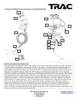
ROPE TO DRUM ATTACHMENT
Route the rope through the davit or anchor rollers to the winch drum. Insert the rope through the metal loop located on the drum
center tube, wrap the rope around the drum center tube and tie in a knot. Pull the rope to confirm your knot is holding as well as
you require. Make sure the rope is not tangled and not looped around anything and is free to wrap on the spool. If no rollers are
present, hold the rope on center of drum about 3 to 6 feet away. While holding light to moderate rope tension, ask a mate to press
the “UP” direction on the switch and hold UP button until the rope is wrapped on the drum. Release the switch button at any time
during the rope loading process, to pause, or if an unsatisfactory wrap is occurring. The installer may wish to load the rope “level-
wind” manor (wrapping the rope back and forth in neat rows on the drum), however when the winch is normally used for anchoring,
the rope will wrap on the drum in a random manor. Wrapping in a random manor will give you a true sense of when the drum is full
and no additional rope or chain will fit. When the rope or chain makes contact with the frame under the drum, no addition rope or
chain will fit without causing the free-fall to stop working correctly.
ANCHOR CHAIN TO ROPE ATTACHMENT
Use a threaded link to attach rope eye-splice to chain and chain to anchor. Some shackles can interfere with anchor docking.


