


User's Manual l MB-COME6-4 UM 0100 l © 2022, TQ-Systems GmbH
Page 17
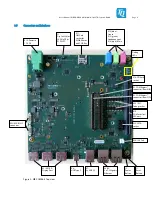
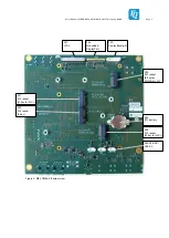
3.5.16
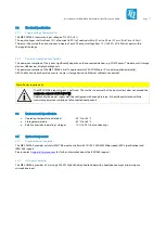
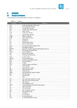
Feature Connector
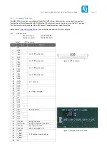
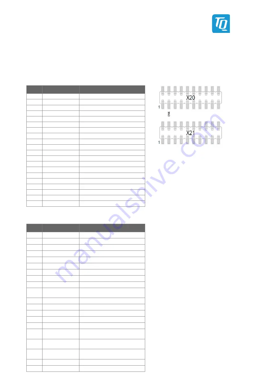
The MB-COME6-4 provides two pin header, where few COM Express™ signals are available.
This connector is for debug and software development purposes. The user can access to SMBus, I
2
C bus and a few other signals.
−
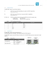
Connector type:
Male Pin header with 2-rows and 2,54 mm pitch
−
Mating connector:
Female Pin header with 2-rows and 2,54 mm pitch
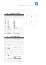
Table 11:
GPIO and COME Signal Connector X20
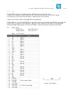
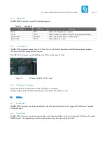
Figure 12: Feature Connectors
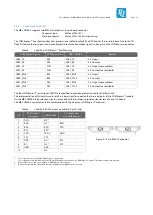
Table 12:
I
2
C and COME Signal Connector X21
Pin
Signal
Remark
1
V_3V3_STBY
3.3 V supply
2
GND
-
3
V_3V3_STBY
3.3 V supply
4
GND
-
5
GPI0
Input
6
GPO0
Output
7
GPI1
Input
8
GPO1
Output
9
GPI2
Input
10
GPO2
Output
11
GPI3
Input
12
GPO3
Output
13
SMB_CK
SM bus clock
14
SUS_S3#
Suspend to RAM
15
SMB_DAT
SM bus data
16
SUS_S4#
Suspend to disk
17
SMB_ALERT#
SM bus alert
18
SUS_S5#
Soft off
19
BATLOW#
Battery low signal
20
COME_WDT
Come Watchdog Timer
Pin
Signal
Remark
1
V_5V_STBY
5 V supply
2
GND
-
3
V_5V_STBY
5 V supply
4
GND
-
5
PWR_BTN#
Power Button
6
GND
-
7
RST_BTN#
Power Button
8
GND
-
9
I2C_CK
COM Express™ I
2
C bus clock
10
BIOS_DIS0#
COM Express™ Boot from carrier SPI
socket.
11
I2C_CK
COM Express™ I
2
C bus clock
12
Wake1#
COM Express™ wake up signal
13
THRMTRIP#
Thermal shutdown signal from module
14
LID#
COM Express™ LID switch
15
SLEEP#
Sleep button signal to module
16
THRM#
COM Express™ input from off-Module
temp sensor
17
SATA_ACT#
COM Express™ Serial ATA (activity
indicator)
18
RAPID_SHUTDOWN
COM Express™ trigger for Rapid
Shutdown
19
-
-
20
-
-


