background image

Assembly Instructions  |  ILM Servo Kits

12

Edition 03/2021 EN

Safety

2.5 Safety instructions for the ILM servo kit

 DANGER

Danger of death by powerful magnetic fields.

The life of persons with passive or active implants such as pacemakers, defibrillators, insu-

lin pumps etc. is put at risk if they stand in the vicinity of the ILM servo kit.


Make sure that no persons who could possibly be affected by powerful magnetic fields 

are able to approach the ILM servo kit. They must maintain a safe distance of at least 

2 m.


Instruct persons in the vicinity of the potential risk.


Attach warning instructions, stating POWERFUL MAGNETIC FIELDS at the installation 

area and storage location.


The rotors of the ILM servo kit will attract other magnetic materials. The forces of 

attraction can be so great that the magnets of the servo kit splinter on impact and 

tiny fragments fly into the eyes.


Wear safety goggles to protect your eyes until you have finished installing the 
ILM servo kit.


If the ILM servo kit is operated below the specified temperature, the magnets can 

become detached from the rotor and fly around due to thermal stressing of the 

adhesive.


Always operate the ILM servo kit within the specified temperature range.


If the ILM servo kit operating voltage is too high, it will exceed the maximum permit-

ted rotational speed. There is a risk of parts becoming detached and flying around.


Always operate the ILM servo kit within the specified voltage and speed ranges.


The electromagnetic interference (EMI) emitted by the ILM servo kit is negligible in 

nominal operation. However it is not possible to entirely exclude the possibility that 

it will affect electrical devices.


Fast acceleration of the ILM servo kit rotor can cause an inadequately secured 

ILM servo kit to move suddenly and be flung out of its original position.


The drive train that is connected to the ILM servo kit must be designed for the max-

imum rotational speed of the ILM servo kit, otherwise the drive train may be dam-

aged or crack.

Содержание ILM Series

Страница 1: ...Assembly Instructions ILM Servo Kits Edition 03 2021 EN ...

Страница 2: ...nformation in this publication is reviewed regularly and any necessary corrections are included in subsequent editions All trademarks mentioned in this manual are the property of their respective owners see section 1 13 on page 9 Copyright TQ Systems GmbH TQ Drives is a trademark of the TQ Group Document item no 304188 0200 TQ Systems GmbH Mühlstr 2 Gut Delling 82229 Seefeld Germany Phone 49 0 815...

Страница 3: ...r 8 1 10 Warranty 8 1 11 Transportation and storage 9 1 12 Environmentally friendly disposal 9 1 13 Trademarks 9 2 Safety 10 2 1 Hazard classification 10 2 2 Target group 10 2 3 Intended use 11 2 4 Working environment and operation 11 2 5 Safety instructions for the ILM servo kit 12 2 6 Warning labels 13 3 Technical data 14 3 1 Data sheet 14 3 2 Connection diagram star serial configuration 14 3 3 ...

Страница 4: ... EN 7 Assembly 19 7 1 Bonding surfaces on stator and rotor 21 7 2 Tools and equipment required 21 7 3 Bonding instructions 22 7 3 1 Stator 22 7 3 2 Rotor 24 7 3 3 Double rotor 25 7 4 Inserting the rotor into the stator 25 8 Declaration of incorporation 26 ...

Страница 5: ...internal rotor motor servo kit consists of a cast stator and a rotor with permanent magnets for installation in ma chines and devices in the commercial environ ment The RoboDrive technology provides the highest power density at maximum torque and overload capability in a compact design The flexible concept offers solutions for a variety of demanding drive applications Alternative nominal currents ...

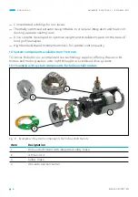
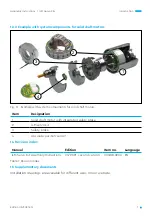
Страница 6: ...s High bandwidth and minimal harmonics for optimal control quality 1 3 System components available from TQ Drives TQ Drives RoboDrive is a complete drive technology supplier offering the servo kit motors and motor gearbox units right through to customised drive systems 1 3 1 Example with system components for hollow shaft motors Fig 2 Example with system components for hollow shaft motors 1 2 3 4 ...

Страница 7: ...motors 1 2 3 4 Item Designation 1 Solid shaft motor with integrated safety brake 2 ILM servo kit 3 Safety brake 4 Absolute position sensor 1 4 Revision index Manual Edition Item no Language ILM Servo Kit Assembly Instructions 03 2021 second version 304188 0200 EN Table 1 Revision index 1 5 Supplementary documents Installation drawings are available for different sizes on our website ...

Страница 8: ...number attached to the rotor 1 10 Warranty TQ Systems GmbH guarantees that if used for the agreed purpose the ILM servo kits fulfil the contractually defined specifications and functionality and correspond to the state of the art at the time of delivery The warranty is limited to material manufacturing and processing defects The manufacturer s liability and warranty shall not apply in the followin...

Страница 9: ...ly be affected by powerful magnetic fields are able to approach the ILM servo kit They must maintain a safe distance of at least 2 m Instruct persons in the vicinity of the potential risk The ILM servo kits must not be disposed of in the residual waste bin In Germany metal and plastic components should be disposed of at the local recy cling centre The national regulations in other EU states should...

Страница 10: ...s important information about the product or about a part of the manual to which particular attention should be paid 2 2 Target group The activities described in this manual must only be carried out by technicians with the following qualifications Training in the installation and commissioning of electrical devices qualified elec trician as defined in EN 50110 1 a person with technical training kn...

Страница 11: ...r reuse for commercial or professional purposes as defined by IEC EN 61000 3 2 Intended use also includes compliance with this manual and the instructions it contains If the ILM servo kits are to be used safely and without interruption they must have been correctly transported stored assembled and set up For any use contrary to the intended use TQ Systems GmbH shall accept no liability for any dam...

Страница 12: ... to protect your eyes until you have finished installing the ILM servo kit If the ILM servo kit is operated below the specified temperature the magnets can become detached from the rotor and fly around due to thermal stressing of the adhesive Always operate the ILM servo kit within the specified temperature range If the ILM servo kit operating voltage is too high it will exceed the maximum permit ...

Страница 13: ...earer Never touch rotating components motor shafts clutches etc Do not wear belts chains ties or clothing with wide sleeves at the workplace Wear a hairnet if you have long hair Make sure that there are no exposed rotating parts Rotating shafts can crack and parts such as screws etc can be flung about Secure rotating shafts with a protective cover Install the ILM servo kit only in a dry environmen...

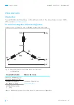
Страница 14: ...n diagram star serial configuration Connections A B and C can be found on the ILM servo kit A B C U1 U2 L1 L3 L2 W1 W2 V1 V2 Fig 4 Measuring points on the ILM servo kit star serial configuration Measured variable Measured values Nominal voltage Un V See data sheet in our download area Nominal current In A Terminal resistance RTT at 20 C mΩ Terminal inductance LTT µH Table 2 Measuring points on the...

Страница 15: ...eter rotor d H7 mm 11 6 11 6 18 18 30 30 42 Rotor length l mm 6 3 9 7 8 1 16 2 9 9 16 1 12 7 Table 3 Installation dimensions part 1 ILM 70x18 ILM 85x04 ILM 85x13 ILM 85x23 ILM 85x26 ILM 115x25 ILM 115x50 Outer diameter stator D js8 mm 69 85 85 85 85 115 115 Board diameter G mm 66 8 82 8 82 8 82 8 82 8 111 8 111 8 Winding head diameter g mm 66 81 81 81 81 110 110 Stator length L mm 30 5 17 6 27 2 3...

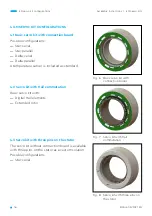
Страница 16: ...mperature sensor is included as standard 4 2 Servo kit with Hall commutation Basic servo kit with Digital Hall elements Extended rotor 4 3 Servo kit with three pins on the stator The servo kit without connection board is available with three pins on the stator as a custom solution Possible configurations Star serial Fig 6 Basic servo kit with connection board Fig 7 Servo kit with Hall commutation ...

Страница 17: ... solder pads on the connection board by way of example Detailed drawings for your type of ILM servo kit are available on our website Fig 9 Solder pads on the connection board Notch Notch Phase A Phase C Phase B A Detail A Temperature sensor 2 SP2 2 SP2 1 5 V voltage supply GND VCC 5 V Hall sensors 1 2 3 SA3 SA2 SA1 Temperature sensor 1 SP1 2 SP1 1 ...

Страница 18: ...or and shaft or stator and housing can also be carried out by TQ Drives if required Stator Rotor shell with magnets Hollow or solid shaft concentricity and radial runout 0 02 mm Bonding rotor and shaft Bonding the stator with thermally conductive adhesive Adhesive injection hole Ø 0 9 mm Leave 8 to 10 mm clearance for wiring Be aware of the effect of the motor s magnetic field on encoders with mag...

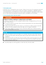
Страница 19: ...tial risk Attach warning instructions stating POWERFUL MAGNETIC FIELDS to the packaging at the installation area and at the storage location DANGER Danger of death by electric shock The ILM servo kit is supplied with electrical voltage for operation Touching live conductors can result in death or severe injuries Use the main switch to switch off all power to the complete system before starting ins...

Страница 20: ...ome time even after the power supply to the entire system is switched off Never detach electrical connections on the ILM servo kit or the inverter while they are live Use a permitted meter to check that the power connections are voltage free before you carry out installation work on the device WARNING Danger of eye injuries caused by splintering magnetic parts The rotors of the ILM servo kit will ...

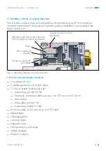
Страница 21: ...sing with thermally conductive adhesive Bonding surface for rotor shaft Adhesive injection hole Ø 0 9 mm Stator Rotor shell with magnets 7 2 Tools and equipment required Non magnetic tool Centring guides for rotor and stator TQ Drives stator bonding kit with Dispensing gun 25 50 ml Thermally conductive adhesive e g LOCTITE Hysol 9497 50 ml Mixing tube Disposable syringe 1 ml Dispensing needle 0 9 ...

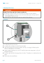
Страница 22: ...talling the ILM servo kit Read and follow the safety data sheets provided with the adhesive 7 3 1 Stator 1 2 Fig 12 Bonding the stator in position Assemble the bonding kit for the TQ Drives stator Clean and degrease the bonding surfaces see Fig 11 on page 21 following the adhesive manufacturer s instructions Apply a bead of adhesive e g LOCTITE 9497 all around the edge item 1 in Fig 12 inside the ...

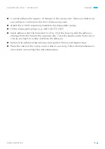
Страница 23: ... Fill the disposable syringe e g with LOCTITE 9497 Inject adhesive into the hole item 2 in Fig 12 in the housing until the adhesive emerges from the hole on the opposite side Twist the needle a little from side to side as you inject to evenly distribute the adhesive Remove the adhesive that emerges and seal both holes with Kapton tape Place the stator in the curing oven so that it cures fully Foll...

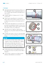
Страница 24: ...rotor Align the rotor so that the indexing hole item 2 in Fig 15 points towards the shaft see Fig 15 Push the rotor item 1 in Fig 15 onto the shaft item 3 in Fig 15 and gently push it as far as it will go NOTE Do not press on the surfaces of the rotor magnets as this will damage their coating Only press on the inner ring item 1 in Fig 16 of the rotor when you push it onto the shaft The pressure po...

Страница 25: ...o prevent sudden movements of the rotor during installation use a mechanical means to lock the rotor in place When inserting the rotor into the stator use a mechanical centring guide to prevent the rotor moving suddenly towards the stator due to magnetic attraction Wear safety goggles to protect your eyes and wear safety gloves until you have fin ished installing the ILM servo kit NOTE Make sure t...

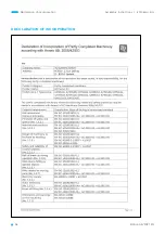
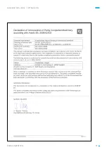
Страница 26: ...Assembly Instructions ILM Servo Kits 26 Edition 03 2021 EN Declaration of incorporation 8 DECLARATION OF INCORPORATION ...

Страница 27: ...Assembly Instructions ILM Servo Kits 27 Edition 03 2021 EN ...

Страница 28: ...Q Drives Mühlstr 2 Gut Delling 82229 Seefeld Germany Phone 49 0 8153 9308 0 Fax 49 0 8153 4223 info tq group com www tq robodrive com TQ Systems GmbH 2021 All data is for information only Technical data subject to change Servo Kit_ILM_MAEN_Rev0103 ...

Отзывы: