14
15
Measurement Procedure:
1.
Disconnect power to the circuit to be measured.
2.
Plug the black test lead into the
COM
input jack.
3
Plug red test lead into the
V
Ω
input jack.
4.
Set rotary switch to the
V
range.
5.
Connect the test leads to the circuit to be mea-
sured.
6.
Reconnect power to the circuit to be measured.
7.
Read the voltage on the 163.
b.
MEASURING AC VOLTS
CAUTION!
Do not attempt to make a voltage measurement if
a test lead is plugged in the A or µmA input jack.
Instrument damage and/or personal injury may
result.
WARNING!
Do not attempt to make a voltage measurement of
more than 750V or of a voltage level that is
unknown.
Instrument set-up:
FUNCTION BLACK RED
MINIMUM
MAXIMUM
TEST LEAD
TEST LEAD
READING
READING
V
COM
V
Ω
0.001V
750V
Application Notes
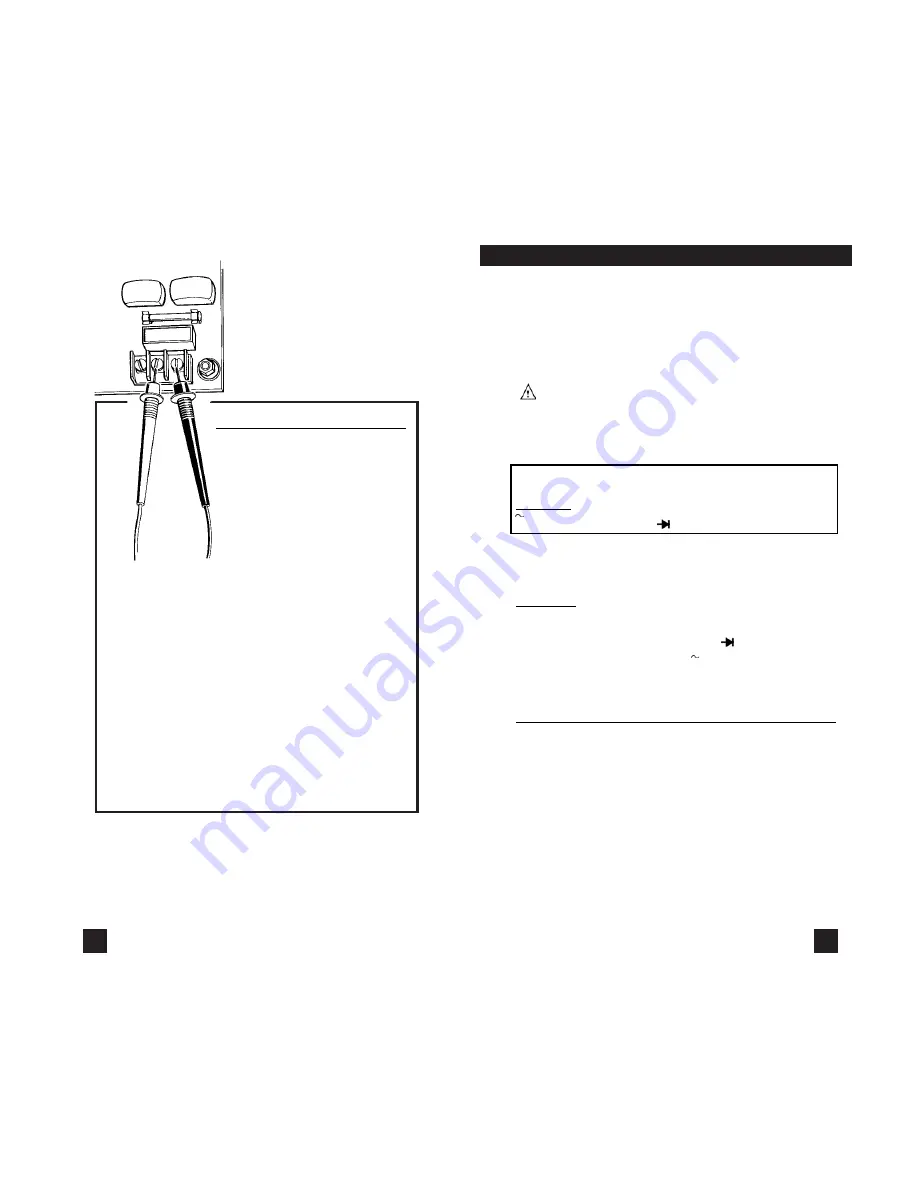
Disconnect power from the termi-
nal block, find the fuse or circuit
breaker that controls the block
and turn it off.
Set up the meter following the
steps under “Measurement
Procedure” on page 15. Then
proceed with the following:
•
Connect the red test lead to the hot side of the
block and the black lead to the neutral side of the
block. Reconnect power to the block and read the
voltage on the meter. The reading should be
approximately 110V to 130V.
•
Disconnect power from the block and move the
red wire to ground. Reconnect power to the
block and read the voltage on the meter. Typically
less than 20V should exist from neutral to
ground. If 110V or above exists, the block may
be wired incorrectly.
www.
GlobalTestSupply
.com
Find Quality Products Online at:


