background image

JetStream L2 Managed Switch

17

Appendix A  Troubleshooting

Appendix A  Troubleshooting

Q1. 

What could I do if I forgot the username and password of the switch?

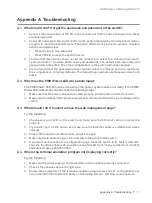
1.  Connect the console port of the PC to the console port of the switch and open a terminal 

emulation program. 

2.  Power off and restart the switch. Perform the action indicated by the terminal emulation 

program to reach the bootUtil menu. The action differs from product to product. Possible 

actions are listed below:
•  Press any key to stop autoboot.
•  Press CTRL-B to reach the bootUtil menu.

3.  The bootUtil menu will be shown. Enter the number 6 to select the “Password recovery” 

option and enter Y to delete all the users and passwords. The default login username and 

password are both admin. The other configurations in the switch will not be changed.

4.  For models without the password recover feature, select the "Reset" option to restore all 

the configurations to factory defaults. The default login username and password are both 

admin.

Q2. 

Why does the PWR/Power LED work abnormally?

The PWR/Power LED should be lit up when the power system works normally. If the PWR/

Power LED worked abnormally, take the following steps:

1.  Make sure that the power cable is connected properly, and the power contact is normal.
2.  Make sure the voltage of the power supply meets the requirement of the input voltage of the 

switch.

Q3. 

What should I do if I cannot access the web management page?

Try the following:

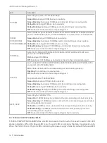
1.  Check every port LED on the switch and make sure the Ethernet cable is connected 

properly.

2.  Try another port on the switch and make sure the Ethernet cable is suitable and works 

normally.

3.  Power off the switch and, after a while, power it on again.
4.  Make sure the IP address of your PC is set within the subnet of the switch.
5.  If you still cannot access the configuration page, reset the switch to its factory defaults. 

Then the IP address of your PC should be set as 192.168.0.x ("x" is any number from 2 to 254) 

and subnet mask as 255.255.255.0.

Q4. 

Why is the terminal emulation program not displaying correctly?

Try the following:

1.  Make sure the power supply is normal and the console cable is properly connected.
2.  Check if the console cable is the right type.
3.  Ensure the parameters of the terminal emulation program are correct: configure Bits per 

second as 38400, Data bits as 8, Parity as None, Stop bits as 1, and Flow control as None.

Содержание Jetstream L2 T2500-28TC

Страница 1: ...Business Networking Solution Installation Guide Jetstream L2 Managed Switch...

Страница 2: ......

Страница 3: ...inistrator Conventions Some models featured in this guide may be unavailable in your country or region For local sales information visit https www tp link com The figures in Chapter 2 and Chapter 3 ar...

Страница 4: ...08 2 2 Safety Precautions 08 2 3 Installation Tools 10 2 4 Product Installation 11 Chapter 3 Connection 13 3 1 Ethernet Port 13 3 2 SFP Port 13 3 3 Console Port 13 3 4 Verify Installation 14 3 5 Power...

Страница 5: ...n fully meet the need of the users demanding higher networking performance T2500G 10MPS T2600G 28MPS is also a Power Sourcing Equipment PSE All the RJ45 ports on the switch support Power over Ethernet...

Страница 6: ...rt 10 100 1000Mbps RJ45 Port Console Port The front panel of T2600G 18TS is shown as the following figure Figure 1 5 Front Panel of T2600G 18TS 10 100 1000Mbps RJ45 Port LEDs Console Port RJ45 USB SFP...

Страница 7: ...000Mbps RJ45 Port LEDs Console Port RJ45 USB SFP Port SFP Port The front panel of The T2600G 52TS is shown as the following figure Figure 1 10 Front Panel of T2600G 52TS Console Console USB 10 100 100...

Страница 8: ...28TS DC T2600G 52TS and ports 1 24 of T2600G 28SQ On A device is linked to the corresponding port and running properly Flashing Transmitting or receiving data Off No device is linked to the correspon...

Страница 9: ...ort Speed or PoE When the PoE LED is on Green On The port is supplying power normally Green Flashing The supply power exceeds the correponding port s maximum power Yellow On Overload or short circuit...

Страница 10: ...port works For T2500 28TC RJ45 ports 25 28 and SFP ports 25 28 are combo ports For T2600G 28SQ RJ45 ports 21 24 and SFP ports 21 24 are combo ports Port Feature Model 10 100 1000Mbps RJ45 Port 10 100M...

Страница 11: ...Related Documents https www tp link com us configuration guides lightning_protection_guide Power Socket Plug the negative connector of the power cord directly into the power socket and plug the posit...

Страница 12: ...device damage and bodily injury caused by improper use you should observe the following rules Safety Precautions Keep the power off during the installation Wear an ESD preventive wrist strap and make...

Страница 13: ...have been taken for the device to prevent static electricity but too strong static electricity can cause deadly damage to the electronic elements on the internal circuit board To avoid the effect of...

Страница 14: ...n measures go to https www tp link com support search the model number of your switch and go to the product Support web page refer to the Lightning Protection Guide from the Related Documents https ww...

Страница 15: ...attach the supplied rubber feet to the recessed areas on the bottom at each corner of the device Figure 2 1 Desktop Installation Feet Bottom of the Device Notch Rack Installation To install the device...

Страница 16: ...kets to the rack as illustrated in the following figure Figure 2 3 Rack Installation Rack Caution Leave 5 to 10 cm gaps around the devices for air circulation Avoid placing heavy things on the device...

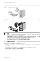
Страница 17: ...Connecting the RJ45 Port RJ45 Port RJ45 Cable 3 2 SFP Port The following figure demonstrates the connection of SFP port to an SFP module Figure 3 2 Inserting the SFP Module SFP Slot SFP Module 3 3 Con...

Страница 18: ...the Console RJ 45 port The Console USB port is hot pluggable while the Console RJ 45 port is not Keep the device power off when plugging the console cable into the Console RJ 45 port Do not connect t...

Страница 19: ...n may differ from the figures above For T2600G 28TS DC Attach the power wires to the DC power input as the following figure shows We recommend you use 22 14 AWG wires Connect the positive pole of the...

Страница 20: ...ge the switch using the GUI Graphical User Interface or using the CLI Command Line Interface To access the switch using the GUI open a web browser and type the default management address http 192 168...

Страница 21: ...works normally If the PWR Power LED worked abnormally take the following steps 1 Make sure that the power cable is connected properly and the power contact is normal 2 Make sure the voltage of the po...

Страница 22: ...MF SMF Except T2600G 52TS 1000BASE SX LX LX10 BX10 MMF SMF 10GBASE SR LR MMF SMF For T2600G 28SQ 10GSFP CU SFP Direct Attach Cable TXC432 CU1M TXC432 CU3M For T2600G 28SQ LEDs T2500 28TC Power System...

Страница 23: ...hargers than those recommended Adapter shall be installed near the equipment and shall be easily accessible Place the device with its bottom surface downward TP Link hereby declares that the device is...

Страница 24: ...2019 TP Link 7106508378 REV4 2 0 For technical support the user guide and more information please visit https www tp link com support or simply scan the QR code...

Отзывы: