Toyota PT228-89460 Скачать руководство пользователя страница 5

TOYOTA 

4-RUNNER 

2006 -  

TOWING HITCH 

Procedure 


Page 5 of 7 pages 

Issue: C  07/06/05 

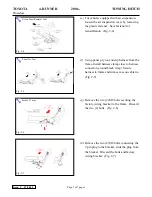
6.  Install Hitch to Frame Rail. 

(a)  Reinstall tie-down bracket to hitch using two 

(2) M12 x 1.25x35 black bolts in driver side 
rear most frame locations.  (Fig. 6-1, Step 1) 

(b) Secure hitch to frame using two (2) M12 x 

1.25x35 black bolts in passenger side rear 
most frame locations.  (Fig. 6-1, Step 2) 

(c)  Hand start four (4) M8 x 1.25 x 25 black 

bolts in forward most frame locations. 
(Fig. 6-1, Step 3) 

(d) Ensure all bolts engage frame spacers and the 

spacers do not impede on frame welds. 

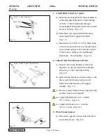
7.  Visually Center Hitch 

(a)  Visually center hitch so that closeout panel is 

centered in fascia cut out.  (Fig. 7-1) 


8.  Tighten Remaining Hitch Hardware. 

(a)  Tighten four (4) M12 bolts in the center to  

60 ± 12 lbf-ft (80 ± 15 N-m). 
(Fig. H-1, Steps 1 - 4) 

(b) Tighten four (4) M12 bolts on the frame rail 

to 60 ± 12 lbf-ft (80 ± 15 N-m). 
(Fig. H-1, Steps 5 - 8). 

(c)  Tighten four (4) M8 bolts to 19 ± 4 lbf-ft  

(25 ± 5 N-m).  (Fig. H-1, Steps 9 - 12) 

Fig. 6-1 

Fig. 7-1 

Fig. 8-1 

Socket, 13 mm, 17 mm; Torque Wrench 

Содержание PT228-89460

Страница 1: ...rotection Notes Safety Glasses Vehicle Protection Cloth Shop Towel Special Tools Notes None Installation Tools Notes Nylon Panel Removal Tool e g Panel Pry Tool 1 Toyota SST 00002 06001 01 Ratchets and Sockets Deep Well 10 mm 12 mm 13 mm 17 mm Socket Wrench Extensions 6 min Torque Wrench x2 0 100 lbf ft 0 100 lbf in Exhaust Hanger Removal Tool e g Snap On P N YA3202 Special Chemicals Notes None Ge...

Страница 2: ...rotection rechecking torque procedure etc Vehicle Disassembly Reassembly panel removal part storage etc Electrical Component Disassembly Reassembly battery disconnection connector removal etc Please see your Toyota dealer for a copy of this document 1 Inspection a Inspect parts for damage 2 Prepare Vehicle for Hitch Installation a Cover exhaust pipe with clean shop towel Fig 2 1 b Caution muffler ...

Страница 3: ...ame Install harness clamp close to harness connector around black wrap Secure harness to frame and trim excess on cable tie Fig 2 5 g Remove the two 2 M8 bolts securing the factory wiring bracket to the frame Discard the two 2 bolts Fig 2 6 h Remove the two 2 M6 bolts connecting the 7 pin plug to the bracket slide the plug from the bracket Discard the bolts and factory wiring bracket Fig 2 7 Fig 2...

Страница 4: ...Bolts can be fed through chain holes Do not tighten Fig 3 1 4 Install 7 Pin Wire Harness to Hitch a Install 7 pin wiring harness removed in Step B 8 to the provided wiring bracket using two 2 M6 1 00x20mm bolts Fig 4 1 b Install wiring bracket to inside surface of the driver side hitch bracket using two 2 M8x1 25x20 black bolts with trapped washers Fig 4 1 c Be sure to feed wiring between the hitc...

Страница 5: ... x 25 black bolts in forward most frame locations Fig 6 1 Step 3 d Ensure all bolts engage frame spacers and the spacers do not impede on frame welds 7 Visually Center Hitch a Visually center hitch so that closeout panel is centered in fascia cut out Fig 7 1 8 Tighten Remaining Hitch Hardware a Tighten four 4 M12 bolts in the center to 60 12 lbf ft 80 15 N m Fig H 1 Steps 1 4 b Tighten four 4 M12 ...

Страница 6: ...nts a Reconnect exhaust to the exhaust hanger ensuring to fully engage the hanger Fig 9 1 b Reinstall the air suspension cover by replacing the one fastener Fig 9 2 1 If fastener is damaged fit a new fastener P N 90467 09185 c Place the hitch plug in the glove box Fig 9 1 Exhaust Hanger Removal Tool Fig 9 2 ...

Страница 7: ...sue C 07 06 05 Accessory Function Checks Inspection torque M12 bolts Inspection torque M8 bolts Inspection torque M6 bolts 7 pin to bracket Frame Spacers Wiring Bracket Hitch Plug 60 12 lbf ft 80 15 N m 19 4 lbf ft 25 5 N m 94 19 lbf in 10 4 2 N m Installed and off of welds Installed and fed between hitch and cross member Placed in glove box ...

Отзывы: