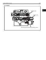
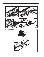
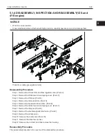
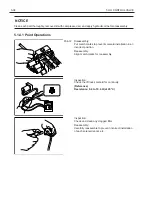
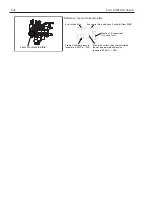
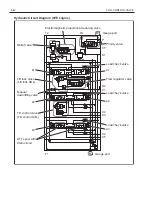
Toyota 62-8FDU15 Скачать руководство пользователя страница 43

5-41

5 OIL CONTROL VALVE

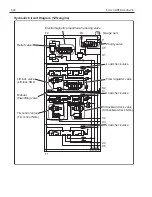
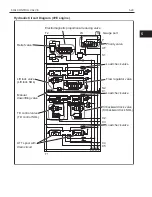
Hydraulic Circuit Diagram (1ZS engine)

T2

LS

R1

P

CF

S1

S2
C1

C2
C3

C4
C5

R2

T1

Electromagnetic proportional reducing valve

Load check valve

Priority valve

Gauge port

Flow regulator valve

Load check valve

a2

a1

b1

b2

b3

a3

Load check valve

Decompression
valve

Tilt control valve
(Tilt control SOL)

Manual 
downlifting valve

Relief valve

Lift lock valve
(Lift lock SOL)

Gauge port

5

Содержание 62-8FDU15

Страница 1: ...8FGU 15 18 20 25 30 32 8FDU 15 18 20 25 30 32 62 8FDU 15 18 20 25 30 8FGCU 20 25 30 32 Pub No CE118 Supplement...

Страница 2: ...ter will be informed by Toyota Industrial Equipment Parts Service News For the service procedures of the mounted engine read the repair manuals listed below as reference together with this manual Ref...

Страница 3: ...ontents 1 GENERAL 2 2 STEERING 5 3 MATERIAL HANDLING SYSTEM 17 4 OIL PUMP 22 5 OIL CONTROL VALVE 25 6 SAS OPS 52 7 DISPLAY 55 8 TROUBLESHOOTING 152 9 WIRING DIAGRAM 203 10 SST LIST AND SERVICE STANDAR...

Страница 4: ...U25 T C 4YE 4YM Gasoline 8FDU25 T C 1ZS Diesel 62 8FDU25 T C 1DZ II Pn3 ton series Pn30 6000 lbs 8FGU30 T C 4YE 4YM Gasoline 8FDU30 T C 1ZS Diesel 62 8FDU30 T C 1DZ II Pn32 6500 lbs 8FGU32 T C 4YE Gas...

Страница 5: ...1 3 1 GENERAL 1 2 FRAME NUMBER Frame No Punching Position Punching position 1...

Страница 6: ...5000 8FGU25 4000 1ZS 8FDU20 8FDU25 60011 5000 8FDU25 4000 1DZ II 62 8FDU20 608FDU25 60011 5000 62 8FDU25 Pn3 ton series 6000 4YE 4YM 8FGU30 8FGU32 60011 6500 8FGU32 6000 1ZS 8FDU30 8FDU32 60011 6500 8...

Страница 7: ...2 5 2 STEERING 2 STEERING 2 1 GENERAL Hydrostatic Steering Valve 1ZS and 4YE engine A A C C B B D D D A A D B B LS C C 2...

Страница 8: ...2 6 2 STEERING 4YM and 1DZ engine W synchronized steering B B A A B B C C C C...

Страница 9: ...EERING 4YM engine L synchronized steering 8 3 1 Neutral position spring 2 Housing 3 Check valve 4 Spool 5 Sleeve 6 Cardan shaft 7 Gear rim 8 Gear wheel rotor 9 Relief valve 1 Shock valve No used 9 2 5...

Страница 10: ...1001 8 2 to 8 7 83 6 to 88 7 1189 to 1262 6 4 to 6 9 65 3 to 70 4 928 to 1001 8 2 to 8 7 83 6 to 88 7 1189 to 1262 8 2 to 8 7 83 6 to 88 7 1189 to 1262 Hydrostatic steering valve W synchronized steeri...

Страница 11: ...2 9 2 STEERING 2 3 COMPONENTS 1ZS and 4YE engine 4507 4YM and 1DZ II engine 4507 2...

Страница 12: ...2 10 2 STEERING PS Valve 1ZS and 4YE engine 4503 4YM engine L synchronized steering 4503 4503 036 CM AT AS 32 AP CK AV AC AD CL 30 CJ AA 31 01K INCL 01...

Страница 13: ...2 11 2 STEERING 4YM and 1DZ II engine W synchronized steering 4503 2...

Страница 14: ...to 80 N m 612 to 816 kgf cm 44 3 to 59 0 ft lbf Disassembly Procedure Step 1 Remove the set bolt and end cover Point 1 Step 2 Remove the gear wheel set drive shaft and distributor plate Point 2 Step...

Страница 15: ...isas sembly 2 Two types of set bolts are used Set bolt with 10 mark on the head Set bolt without any mark on the head Use a rod tip bolt with no mark on its head at pos ition A in the illustration at...

Страница 16: ...lates in this order from the depth Reassembly When inserting the sleeve W spool into the valve body apply MP grease to the packing ring inner sur face portion in sliding contact with the spool and dus...

Страница 17: ...lus trated directions Reassembly Apply MP grease to the ring before assembling with the packing Apply MP grease to the outer periphery of the packing Reassembly Guide the packing W ring to the assembl...

Страница 18: ...e and connect the SST adapter SST 09450 23320 71 2 Install the oil pressure gauge Plug size PT1 8 Step 2 Start the engine rotate the steering wheel slowly clockwise and counterclockwise and inspect th...

Страница 19: ...IRCUIT DIAGRAM 17 3 2 COMPONENTS 21 3 1 HYDRAULIC CIRCUIT DIAGRAM 4YE and 1ZS engine Without oil cooler 3 7 1 8 2 4 5 6 1 Oil pump 2 Priority valve 3 Oil control valve 4 Steering valve 5 Solenoid valv...

Страница 20: ...SYSTEM With oil cooler 3 7 1 8 2 4 5 6 10 9 1 Oil pump 2 Priority valve 3 Oil control valve 4 Steering valve 5 Solenoid valve OPT 6 Power steering cylinder 7 Lift tilt and ATT cylinder 8 Oil tank 9 Oi...

Страница 21: ...LING SYSTEM 4YM and 1DZ II engine Without oil cooler 3 7 1 8 2 4 5 6 1 Oil pump 2 Flow divider 3 Oil control valve 4 Steering valve 5 Solenoid valve OPT 6 Power steering cylinder 7 Lift tilt and ATT c...

Страница 22: ...SYSTEM With oil cooler 3 7 1 8 2 4 5 6 10 9 1 Oil pump 2 Flow divider 3 Oil control valve 4 Steering valve 5 Solenoid valve OPT 6 Power steering cylinder 7 Lift tilt and ATT cylinder 8 Oil tank 9 Oil...

Страница 23: ...3 21 3 MATERIAL HANDLING SYSTEM 3 2 COMPONENTS 6801 3...

Страница 24: ...4 22 4 OIL PUMP 4 OIL PUMP 4 1 GENERAL 22 4 2 SPECIFICATIONS 23 4 3 PERFORMANCE TEST 24 4 1 GENERAL 4Y STD 1ZS 1DZ II...

Страница 25: ...pump single gear 24 0 1 464 Steel cabin KYB DGP2323 Gear pump double gear 22 9 1 397 4YM KYB KFS2427 Gear pump single gear 27 8 1 696 1ZS KYB KFS2424 Gear pump single gear 24 0 1 464 1DZ II KYB KFS24...

Страница 26: ...600 118 640 126 565 111 600 118 575 113 600 118 4YM 600 118 640 126 565 111 600 118 575 113 600 118 1ZS 615 121 655 129 590 116 630 124 600 118 640 126 1DZ II 615 121 655 129 590 116 630 124 600 118...

Страница 27: ...5 25 5 OIL CONTROL VALVE 5 OIL CONTROL VALVE 5 1 OIL CONTROL VALVE ASSY 26 5 2 OIL CONTROL VALVE ASSY MINI LEVER AND JOYSTICK LEVER 39 5 3 RELIEF PRESSURE ADJUSTMENT 50 5...

Страница 28: ...5 26 5 OIL CONTROL VALVE 5 1 OIL CONTROL VALVE ASSY 5 1 1 GENERAL 1ZS and 4YE engine T2 CF S2 P R C1 LS S1 C3 C5 T1 C2 C4 X1 X2 X3 X4 X1 X2 X3 X4...

Страница 29: ...5 27 5 OIL CONTROL VALVE X1 X1 INLET Priority valve Relief valve Electromagnetic proportional reducing valve 5...

Страница 30: ...T1 Electromagnetic proportional reducing valve Load check valve Priority valve Gauge port Flow regulator valve Load check valve Tilt backward lock valve Tilt backward lock SOL Load check valve Tilt co...

Страница 31: ...ic proportional reducing valve Load check valve Priority valve Gauge port Flow regulator valve Load check valve Tilt backward lock valve Tilt backward lock SOL Load check valve Tilt control valve Tilt...

Страница 32: ...59 Flow regulator flow volume L min US gal min 50 13 2 60 15 8 75 19 8 Lowering speed specification mm sec fpm V Pn No load 550 108 500 98 500 98 Loaded 500 98 500 98 500 98 V Cu No load 500 98 500 98...

Страница 33: ...5 31 5 OIL CONTROL VALVE 5 1 3 COMPONENTS 1ZS and 4YE engine ASSY FITTING 6705 1DZ II and 4YM engine ASSY FITTING 6705 5...

Страница 34: ...5 32 5 OIL CONTROL VALVE 1DZ II and 4YM engine INLET OUTLET LIFT TILT 6705 1DZ II and 4YM engine ATT 6705...

Страница 35: ...p 2 Remove the lift limit switch and spring cover Point 3 Step 3 Remove the lift spool Point 4 Step 4 Remove the tilt control SOL Point 5 Step 5 Remove the backward tilt lock SOL Point 6 Step 6 Remove...

Страница 36: ...Disassembly Put match marks to prevent solenoid installation in an incorrect position Reassembly Align match marks for reassembly Inspection Check the lift lock solenoid for continuity Reference Resi...

Страница 37: ...No continuity when the switch is pressed Reassembly Be careful not to mistake the lowering side and lifting side SST Washer Point 4 Disassembly and Reassembly Remove the compression spring from the l...

Страница 38: ...at 20 C Inspection Check and clean any clogged filter Reassembly Carefully reassemble to prevent incorrect installation of each solenoid spool 1 2 3 4 Point 7 Inspection Check the tilt limit switch fo...

Страница 39: ...Point 10 Inspection Check and clean any clogged filter a Adjusting screw A Lock nut 1 Adjusting sleeve B Lock nut 2 Reassembly When the relief valve is disassembled temporarily in stall it after fitt...

Страница 40: ...of current to plate 4 unit of short No 5 unit serial No and whose 5 unit start from 00001 Stamp 3 unit aim pressure Mention I P current rank H L each 1unit Stamp the current value that calculated tha...

Страница 41: ...5 39 5 OIL CONTROL VALVE 5 2 OIL CONTROL VALVE ASSY MINI LEVER AND JOYSTICK LEVER 5 2 1 GENERAL 1ZS and 4YE engine T2 CF S2 P R C1 LS S1 C3 C5 T1 C2 C4 X1 X2 X3 X4 X1 X2 X3 X4 5...

Страница 42: ...5 40 5 OIL CONTROL VALVE X1 X1 INLET Priority valve Relief valve Electromagnetic proportional reducing valve...

Страница 43: ...T1 Electromagnetic proportional reducing valve Load check valve Priority valve Gauge port Flow regulator valve Load check valve a2 a1 b1 b2 b3 a3 Load check valve Decompression valve Tilt control valv...

Страница 44: ...Electromagnetic proportional reducing valve Load check valve Priority valve Gauge port Flow regulator valve Load check valve a2 a1 b1 b2 b3 a3 Load check valve Tilt control valve Tilt control SOL ATT...

Страница 45: ...9 Flow regulator flow volume L min US gal min 50 13 2 60 15 8 75 19 8 Lowering speed specification mm sec fpm V Pn No load 550 108 500 98 500 98 Loaded 500 98 500 98 500 98 V Cu No load 500 98 500 98...

Страница 46: ...5 44 5 OIL CONTROL VALVE 5 2 3 COMPONENTS 1ZS and 4YE engine ASSY FITTING 6705...

Страница 47: ...he lift lock SOL and flow regulator valve Point 2 Step 2 Remove the tilt control SOL Point 3 Step 3 Remove the proportional solenoid a Point 4 Step 4 Remove the proportional solenoid b Point 5 Step 5...

Страница 48: ...Disassembly Put match marks to prevent solenoid installation in an incorrect position Reassembly Align match marks for reassembly Inspection Check the lift lock solenoid for continuity Reference Resi...

Страница 49: ...gged filter Inspection Check and clean any clogged orifice Reassembly Carefully reassemble to prevent incorrect installation of each solenoid spool 1 2 5 6 3 7 Point 4 Inspection Check the proportiona...

Страница 50: ...continuity Measurement terminal 1 5 Continuity exists Measurement terminal 2 6 Continuity exists Measurement terminal 3 7 Continuity exists A Adjusting screw A Disassembly Before disassembly measure...

Страница 51: ...1 for tilt relief pressure adjustment because the adjustment is not necessary When replacing the relief valve change the setting value H and L rank it is necessary Refer to chapter of the display for...

Страница 52: ...ressure gauge Remove the oil pressure detecting plug installed on the left side of the oil control valve and install the oil pressure gauge there Plug size 9 16 18UNF Fitting size 9 16 18UNF PF1 4 Fit...

Страница 53: ...ft lever to lift the fork fully 3 While running the engine at the maximum speed op erate the lift lever to the lifting side Gradually tighten adjusting sleeve B to make the oil pressure in the re lief...

Страница 54: ...6 52 6 SAS OPS 6 SAS OPS 6 1 SAS FUNCTION 6 1 1 COMPONENTS Load Sensor 4Y engine 5803 Load Sensor 1ZS engine 5803...

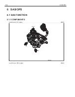
Страница 55: ...6 53 6 SAS OPS 6...

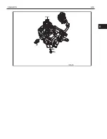
Страница 56: ...6 54 6 SAS OPS Load Sensor 1DZ II engine 5803...

Страница 57: ...eeling adjustments and specification setting as a service function On this model a graphic LCD Liquid Crystal Display has been adopted and this provides various informa tion to be easy to understand w...

Страница 58: ...indicator Auto speed control indicator Eco mode indicator NEW Planned maintenance hour warning indicator Menu lock indicator NEW Meter Odometer Trip meter Planned maintenance hour meter Warning funct...

Страница 59: ...1 second after the key switch is turned ON 7 1 3 2 Status screen The status screen is displayed after the initial screen Function activation indicator Speedometer Function activation indicator Low sp...

Страница 60: ...hen the oper ator presses the low speed setting switch This indicator lights when the low speed setting is effective and the vehicle speed is limited at a preset level In case this setting is level 8...

Страница 61: ...switch is turned on under the above condition However the buzzer doesn t sound at that time when the elapsed time has just exceeded the preset hour while the vehicle is in operation The indicator is d...

Страница 62: ...ing default models are preset in mile And export SPEC OPT E E C SPEC OPT mm kg indicator SPEC OPT are preset in km h 3 Planned maintenance hour meter The planned maintenance hour meter displays preset...

Страница 63: ...que Converter oil temperature overheat warning The indicator blinks when the oil temperature level be comes more than or equal to level 9 approx 120 degrees C The entire gauge blinks at level 10 appro...

Страница 64: ...eturns 1 Low speed level setting screen switch 2 switch 3 switch 4 The low speed level setting function is set up on this screen Switch 2 Select the lower level Switch 3 Select the higher level Switch...

Страница 65: ...trator s Second Password Switching of Menu Lock When menu lock setting is released the operator can set it 7 1 6 2 Administrator password Password Entry Procedure NOTICE If an operation error occurs d...

Страница 66: ...PLAY Step Display Operation Vehicle response 5 When the second password has been set password screen is displayed Enter the password Other Skip this screen 6 Administrator menu screen is displayed aut...

Страница 67: ...DISPLAY 7 1 6 3 Setting menu for administrator Use switch 1 to select the desired item and press switch 4 each setting screen will appear Select END on the menu and press switch 4 the status screen re...

Страница 68: ...peed limiter setting screen switch 2 switch 3 switch 4 The travel speed limiter level is set on this screen Switch 2 Select the lower level Switch 3 Select the higher level Switch 4 Display the menu s...

Страница 69: ...lue same The function is turned off when 10h is set for maintenance hour meter and the switch 2 is pressed to decrease the setting time The current value is kept but the maintenance indicator and the...

Страница 70: ...econd password can be registered by continuing to press switch 1 for 2 seconds after entering the password by using switch 1 to 4 If the switch 4 is pressed for 2 seconds or more before re gistration...

Страница 71: ...T displayed Eco mode is NOT changed Menu lock indicator is displayed on the status screen when menu lock setting is YES Switch 2 Selecting Yes Switch 3 Selecting No Switch 4 Returning to menu screen C...

Страница 72: ...ng Yes Switch 3 Selecting No Switch 4 Returning to menu screen Conditions to release Menu lock vary by optionset items MENULOCK SPEC In factory setting MENU LOCK SPEC is preset in A on US domestic mod...

Страница 73: ...ning TUNING Makes fine adjustment of trav eling and material handling functions 2 As reques ted by cus tomer Option Setting OPTIONSET Specification set ting Sets each vehicle option and other specific...

Страница 74: ...or the multi function display 4 During the condition that is listed in matching 5 When tire size is changed or tire is replaced 6 When removing installing or replacing oil control valve 7 2 2 PASSWORD...

Страница 75: ...When pressing the switches a short beep sounds and after 2 seconds repeated short beeps sound 5 When the service second password MASK PASS WORD has been set Password screen is displayed Enter the pas...

Страница 76: ...er the password on the general screen to display the service function MASK MENU screen Switch 1 Switch 4 Step 2 Select a desired function using switch 1 Then press switch 4 set to display the function...

Страница 77: ...DISPLAY 1 ANALYZER This function indicates the electrical system status and reads the error information detected by the controller Switch 1 Switching selection to next item Switch 4 To ANALYZER MENU s...

Страница 78: ...and material handling Switch 1 Switching selection to next item Switch 4 To TUNING MENU screen 3 OPTIONSET Use this function to match control of the controller or dis play according to the set options...

Страница 79: ...xt item Switch 4 To MATCHING MENU screen 5 WHEEL RADIUS This function rewrites the tire information in the controller for correcting the speed indication odometer and trip meter Switch 1 Switching sel...

Страница 80: ...e mask second password Switch 1 Switching selection to next item Switch 4 To MASK PASSWORD screen 9 MANAGER PASS CLR Deletes the manager second password Switch 1 Switching selection to next item Switc...

Страница 81: ...ance hour meter Switch 1 Switching selection to next item Switch 4 To METER START screen NOTICE After start counting the meters METER START will not be displayed on the service function MASK MENU scre...

Страница 82: ...ng 2 In Out monitor function I O MONITOR This function displays the analog input values from individual sensors in the traveling material handling FHPS SAS and OPS systems Monitoring the displayed val...

Страница 83: ...take air temperature THW Coolant temperature sensor voltage THW Coolant temperature PIM Intake pipe negative pressure sensor voltage PIM Intake manifold pressure 4 10 VPA1 Accelerator pedal position s...

Страница 84: ...ing speed BATT Battery voltage PA Accelerator pedal position THW Coolant temperature 2 5 ATM Atmospheric pressure PIM Intake manifold pressure past turbocharger MAF Intake air mass THA Intake air temp...

Страница 85: ...g speed ACCSW Accelerator switch BRKSW Brake switch PKBSW Parking brake switch SPARE Spare 2 3 SEAT Seat switch DRF Forward traveling switch DRR Reverse traveling switch RYF Forward reverse traveling...

Страница 86: ...er angle sensor 2 voltage TPSOL Tilt proportional valve solenoid current TSOL Tilt solenoid 5 7 POTA1 Attachment 1 lever angle sensor 1 voltage At tachment 1 lever angle sensor 2 voltage A1SOL Attachm...

Страница 87: ...y forced operation BUZZER Warning buzzer forced operation SWG TEST LMP Swing lock operation check RELIEF SOL Electromagnetic relief valve forced operation 8 VERSION Program version 1 1 DISPLAY Display...

Страница 88: ...ext item Switch 4 To I O TRAVELING screen 4 I O M HANDLING Switch 1 Switching selection to next item switch 4 To I O M HANDLING screen 5 I O STEERING Switch 1 Switching selection to next item Switch 4...

Страница 89: ...ted on the screen and press enter switch 4 to display DIAG MEMORY 1 2 screen Step 3 Press switch 4 on DIAG MEMORY 2 2 screen to return to the ANALYZER MENU screen NOTICE When no error codes are displa...

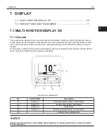
Страница 90: ...7 88 7 DISPLAY DIAG MEMORY 2 2 Displays diagnosis 6 to 10 Switch 4 Returning to the ANALYZER MENU screen...

Страница 91: ...of the 4Y engine controller switch various input values including input voltage from the sensor correction value of the control and output condition to the relay Operating Procedure Step 1 Display the...

Страница 92: ...type ADJ Engine specification discrimination signal Displays states of engine specification discrimination sig nal Switch 4 To I O ENGINE CTRL 2 10 screen I O ENGINE CTRL 2 10 MREL EFI main relay dri...

Страница 93: ...rd Display Accelerator pedal position sensor 1 voltage standard Accelerator sensor 1 voltage standard 0 2 to1 3 V when accelerator is not operated 1 4 to 4 1 V during maximum pressing of accelerator A...

Страница 94: ...e idle after warm up IM Electronic throttle motor current Displays current flowing to the electronic throttle motor Standard 0 2 to 10 0 A Switch 4 To I O ENGINE CTRL 6 10 screen I O ENGINE CTRL 6 10...

Страница 95: ...CTRL 6 10 PIM Intake pipe negative pressure sensor voltage Intake manifold pressure refer to I O ENGINE CTRL 3 10 VF VF voltage LPG CNG Displays the voltage V output from VF terminal Standard 2 0 to 3...

Страница 96: ...screen NOTICE You cannot move directly from I O ENGINE CTRL screen to the screen of the other items Return to ANALYZER MENU screen once then move to screen of each item I O ENGINE CTRL 1 5 NE Engine s...

Страница 97: ...level THF Fuel Temperature C Display fuel Temperature QF Fuel injection quantity Display fuel injection quantity Switch 4 To I O ENGINE CTRL 4 5 screen I O ENGINE CTRL 4 5 NE Engine speed rpm Traveli...

Страница 98: ...perating Procedure Step 1 Display the ANALYZER MENU screen Switch 1 Switch 4 Step 2 Press switch 1 twice to check that 3 I O TRAVEL ING is selected and press enter switch 4 to dis play I O TRAVELING 1...

Страница 99: ...pedal type BRKSW Brake switch Display states of brake switch Vehicle without brake switch BRKSW 0 Always Vehicle with brake switch BRKSW 1 ON when brake pedal is depressed BRKSW 0 OFF when brake peda...

Страница 100: ...eling position Displayed code DRF 1 ON DRR 0 OFF Direction lever Neutral position Displayed code DRF 0 OFF DRR 0 OFF Direction lever Reverse travel position Displayed code DRF 0 OFF DRR 1 ON RYF Forwa...

Страница 101: ...ate SWN 0 OFF Non energized swing lock state PRES Load sensor voltage and MPa display Displays input voltage from the load sensor to the control ler and detected pressure Standard at no load 0 5 to 4...

Страница 102: ...nsors Operating Procedure Step 1 Display the ANALYZER MENU screen Switch 1 Switch 4 Step 2 Press switch 1 3 times to check that 4 I O M HANDLING is selected and press enter switch 4 to display I O M H...

Страница 103: ...lt switch STD lever vehicle Tilt lever Forward tilt position Displayed code MF 1 ON MR 0 OFF Tilt lever Neutral position Displayed code MF 0 OFF MR 0 OFF Tilt lever Backward tilt position Displayed co...

Страница 104: ...FF 0 OFF TSOL 0 OFF 0 OFF 0 OFF 1 ON 0 OFF 1 ON 0 OFF BTSL SEAT 1 ON 1 ON 1 ON 1 ON 1 ON 1 ON 0 OFF I O M HANDLING 2 7 MA Tilt angle sensor voltage V Displays the input voltage from the tilt angle sen...

Страница 105: ...to 0 85 A LSOL Lift lowering lock solenoid Refer to I O M HANDLING 1 7 Switch 4 To I O M HANDLING 4 7 screen I O M HANDLING 4 7 POTT Tilt lever angle sensor 1 voltage V tilt lever angle sensor 2 volta...

Страница 106: ...side Attachment 1 lever angle sensor 1 voltage 1 8 to 4 1 V Attachment 1 lever angle sensor 2 voltage 0 3 to 2 9 V Attachment 1 lever Forward tilt side Attachment 1 lever angle sensor 1 voltage 0 4 to...

Страница 107: ...ide Attachment 2 lever angle sensor 1 voltage 1 8 to 4 1 V Attachment 2 lever angle sensor 2 voltage 0 3 to 2 9 V Attachment 2 lever Forward tilt side Attachment 2 lever angle sensor 1 voltage 0 4 to...

Страница 108: ...l hand ling 0 3A to 0 75A MU Lift raising switch Displays status of lift raising switch Refer to I O M HANDLING 1 7 Mini lever Joystick vehicle MALL Material handling operations switch Displays status...

Страница 109: ...to check that 5 I O STEER ING is selected and press enter switch 4 to dis play I O STEERING 1 1 screen NOTICE You cannot move directly from I O STEER ING screen to the screen of the other items Return...

Страница 110: ...on 360 of the steering wheel is divided by 160 and the value is set to 80 when the knob is in the position as indicated in the illustration Vehicle without synchronized steering K POS Always Vehicle w...

Страница 111: ...hour meter value BATT Battery voltage V Displays battery voltage Standard 8 0 to 16 0V THO Torque converter oil temperature sensor voltage V and oil temperature C Displays input voltage from the torq...

Страница 112: ...OAD SOL Unused OPTION RLY T C interlock relay forced operation 4 ON Traveling is possible OFF Traveling is not pos sible BUZZER 3 Warning buzzer forced operation ON Buzzer ON OFF Buzzer OFF SWG TEST L...

Страница 113: ...he ANALYZER MENU screen Switch 1 Switch 2 Switch 4 Switch 3 Step 2 Press switch 1 6 times to check that 7 ACTIVE TEST is selected and press enter switch 4 to dis play ACTIVE TEST 1 3 screen Switch 1 M...

Страница 114: ...tch 4 Returning to ANALYZER MENU screen ACTIVE TEST 2 3 NOTICE When performing ACTIVE TEST 2 3 item make sure to sit on the seat correctly If not OPS is activated and material handling operation may b...

Страница 115: ...olenoid operation display Check the swing lock operation states according to travel ing and material handling states by OPS light Vehicle without swing lock Unused Vehicle with swing lock ON Indicated...

Страница 116: ...itch 4 Returning to ANALYZER MENU screen NOTICE You cannot move directly from VERSION screen to the screen of the other items Re turn to ANALYZER MENU screen once then move to screen of each item VERS...

Страница 117: ...tem Level initial setting value 1 2 3 4 5 6 7 8 LIFT DOWN START Lift lowering adjustment 1 Play at the beginning of lift down operation Wide Small INCH Lift lowering adjustment 2 Inching speed during...

Страница 118: ...Backward tilt adjustment 3 Maximum speed during tilt backward oper ation Slow Fast ACC Backward tilt adjustment 4 Acceleration speed during tilt backward operation Weak Strong DEC Backward tilt adjus...

Страница 119: ...trong DEC Attachment 1 lever backward tilt side ad justment 5 Deceleration speed during the attachment 1 lever pull operation Weak Strong ATT2 PUSH START Attachment 2 lever forward tilt side ad justme...

Страница 120: ...Strong DEC Attachment 2 lever backward tilt side ad justment 5 Deceleration speed during the attachment 2 lever pull operation Weak Strong ATT3 PUSH START Attachment 3 lever forward tilt side ad justm...

Страница 121: ...justment 4 Acceleration speed during the attachment 3 lever pull operation Weak Strong DEC Attachment 3 lever backward tilt side ad justment 5 Deceleration speed during the attachment 3 lever pull ope...

Страница 122: ...tch 4 To tuning level setting screen 4 ATT1 LEVER Mini lever Joy stick vehicles only Switch 1 Switching selection to next item Switch 4 To tuning level setting screen 5 ATT2 LEVER Mini lever Joy stick...

Страница 123: ...hat 1 GENERAL is selected and press enter switch 4 to display TUNE GEN screen NOTICE You cannot move directly from level setting screen of GENERAL to the screen of the other items Return to TUNING MEN...

Страница 124: ...CE You cannot move directly from level setting screen of LIFT LEVER to the screen of the other items Return to TUNING MENU screen once then move to level setting screen of each item LIFT DOWN Lift dow...

Страница 125: ...NOTICE You cannot move directly from level setting screen of TILT LEVER to the screen of the other items Return to TUNING MENU screen once then move to level setting screen of each item TILT FWD Tilt...

Страница 126: ...ICE You cannot move directly from level setting screen of ATT1 LEVER to the screen of the other items Return to TUNING MENU screen once then move to level setting screen of each item ATT1 PUSH Attachm...

Страница 127: ...CE You cannot move directly from level setting screen of ATT2 LEVER to the screen of the other items Return to TUNING MENU screen once then move to level setting screen of each item ATT2 PUSH Attachme...

Страница 128: ...E You cannot move directly from level setting screen of ATT3 LEVER to the screen of the other items Return to TUNING MENU screen once then move to level setting screen of each item ATT3 PUSH Attachmen...

Страница 129: ...to enable disable buzzer sound when seat switch is off YES Enabled Default NO Disabled PKB BUZZER 1 Setting to enable disable park ing brake off warning YES Enabled NO Disabled CONV BUZZER Unused TEMP...

Страница 130: ...1 These are set according to the vehicle specification at the time of shipment 2 4Y engine equipped model only 3 Mini lever Joystick specification vehicle only 4 Please set this setting to the number...

Страница 131: ...to next item Switch 2 Setting from NO to YES Switch 3 Setting from YES to NO Switch 4 Returning to service function MASK MENU screen Option set screen 3 Switch 1 Switching selection to next item Swit...

Страница 132: ...SPLAY Option set screen 5 Switch 1 Switching selection to next item Switch 2 Setting 5 4 3 2 3 4 2 3 NO to YES Switch 3 Setting 2 3 4 5 2 3 3 4 YES to NO Switch 4 Returning to service function MASK ME...

Страница 133: ...etic relief valve EMRV is set for each electromagnetic relief valve before shipping and it is registered to SAS OPS controller So MATCHING is necessary when maintaining or replacing parts for electrom...

Страница 134: ...sensor 11 When replacing attachment 1 lever angle sensor 12 When replacing attachment 2 lever angle sensor 13 When removing installing or replacing oil control valve 7 2 6 3 BEFORE STARTING MATCHING...

Страница 135: ...hment at a height of 500 mm 19 7 in and perform relief at the topmost posi tion Set the mast in the vertical position from the backward tilted position by operating the tilt lever in the forward tilti...

Страница 136: ...witch 1 and press enter switch 4 to move to the service function MASK MENU setting screen of the selected item Step 4 Press enter switch 4 while selecting 4 END menu to return to service function MASK...

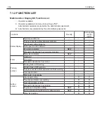
Страница 137: ...7 135 7 DISPLAY NOTICE 2 MINI LEVER will not be displayed other than on mini lever and joystick specification vehicle 7...

Страница 138: ...You cannot move directly from each matching set screen of SAS to the matching set screen of the other items Return to MATCH ING MENU screen once then move to match ing set screen of each item TILTL LE...

Страница 139: ...matching is performed press switch 1 OK is indic ated on the display Switch 1 Pressing this for more than 2 seconds will per form matching Switch 4 To SWING LEVEL screen SWING LEVEL Screen Unused Swit...

Страница 140: ...urrent vehicle condi tion value NOTICE You cannot move directly from each matching set screen of MINI LEVER to the matching set screen of the other items Return to MATCHING MENU screen once then move...

Страница 141: ...seconds will per form matching Switch 4 Returning to MATCHING MENU screen NOTICE LEVER4 screen will be displayed according to the number of ways being set 7 2 6 7 MATCHING EMRV EMRV Perform the settin...

Страница 142: ...f short No 5 unit serial No and whose 5 unit start from 00001 Stamp 3 unit aim pressure Mention I P current rank H L each 1unit Stamp the current value that calculated than an approximate expression e...

Страница 143: ...1 Enter the password on the general screen to display the service function MASK MENU screen Switch 1 Switch 2 Switch 4 Switch 3 Step 2 Press switch 1 4 times to check that 5 WHEEL RADIUS is selected...

Страница 144: ...LID 348 3 0 ton model 28X9 15 12PR STD 361 WIDE TREAD 361 28X9 15 7 00 SOLID 365 WIDE TREAD SOLID 365 29X8 15 12PR DUAL 390 DUAL SOLID 387 Cushion 1 0 ton model 18X6X12 1 8 STD 240 NON MARKING 240 SMO...

Страница 145: ...ted and press enter switch 4 to display the SPEED LIMIT SET screen Step 3 Change the speed limit to desired value with switch 2 and switch 3 and press enter switch 4 to set the value and return to ser...

Страница 146: ...MENU screen Switch 1 Switch 2 Switch 4 Switch 3 Step 2 Press switch 1 6 times to check that 6 IDLE AD JUSTMENT is selected and press enter switch 4 to display the IDLE ADJUSTMENT screen IDLE ADJUSTMEN...

Страница 147: ...f shipment Operating Procedure Step 1 Enter the password on the general screen to display the service function MASK MENU screen Switch 1 Switch 4 Step 2 Press switch 1 7 times to check that 8 MASK PAS...

Страница 148: ...d password setting screen press switch 1 for two seconds or more without any digits entered The password is deleted and OK is displayed after the opera tion NOTICE The delete mask second password oper...

Страница 149: ...hat you are ready for the set password operation Press switch 1 for two seconds or more to perform Pass word Set When the setting is completed OK is dis played NOTICE Password Set is not possible unti...

Страница 150: ...general screen to display the service function MASK MENU screen Switch 1 Switch 4 Step 2 Press switch 1 8 times to check that 9 MANAGER PASS CLR is selected and press enter switch 4 to display the MAN...

Страница 151: ...o display the CONTRAST screen NOTICE After completing the meter start setting 11 METER START will not be displayed on the service function MASK MENU screen Switch 1 Switch 2 Switch 4 Switch 3 Step 3 C...

Страница 152: ...2 Press switch 1 10 times to check that 11 METER START is selected and press enter switch 4 to display the METER START screen NOTICE The speed limit of the Low speed level setting function is 8OFF whe...

Страница 153: ...mpleted Step 5 Press switch 4 to return to service function MASK MENU screen NOTICE After completing the meter start setting METER START will not be displayed on the service function MASK MENU screen...

Страница 154: ...8 152 8 TROUBLESHOOTING 8 TROUBLESHOOTING 8 1 DIAGNOSIS CODE LIST 153 8 2 WARNING LIST 154 8 3 WHEN NO ERROR CODE IS DISPLAYED 155 8 4 WHEN ERROR CODE IS DISPLAYED 189...

Страница 155: ...rmality P port 61 4 61 4 Blinking SAS OPS Pressure sensor VCC short abnormality P port EC 1 EC 1 Blinking SAS OPS Unload solenoid open circuit or load short abnormality EC 2 EC 2 Blinking SAS OPS Elec...

Страница 156: ...except lifting disabled High battery voltage Use a bat tery of the specified voltage On SAS OPS Swing lock control is always locked Low battery voltage Charge or replace the battery On SAS OPS Tilt op...

Страница 157: ...8 155 8 TROUBLESHOOTING 8 3 WHEN NO ERROR CODE IS DISPLAYED Defect causes related to SAS OPS 8...

Страница 158: ...nsor installa tion Link installation part destroyed damaged Accelerator pedal position check Check the opening degree of the accel erator pedal when not operated If not close to 0 installation check o...

Страница 159: ...limit setting Change SAS OPS con troller Controller defect Replace Travel and load handling control For vehicles with travel and load handling control Despite being loaded at high lifting height the...

Страница 160: ...check or re place switch Display setting Maximum speed limiter speed limiter setting enabled Check the setting content of the max imum speed limiter check the setting content of the speed limit settin...

Страница 161: ...Disconnection fault Harness connector ON OFF check with analyzer Harness check or re place switch 4YE 1ZS engine model Mini lever or Joy stick When lifting a heavy load it is unable to lift upward or...

Страница 162: ...leak fault Harness connector Load sensor voltage check Mount a load ground the forks and check the change in voltage If there is no change perform a harness check or re place the sensor 4YE engine mod...

Страница 163: ...s connector Harness check or re place buzzer Display setting OPS leaving seat notification buzzer setting disabled Check setting values with option set Change SAS OPS con troller Controller defect Rep...

Страница 164: ...wer sup ply side lead in side Disconnection fault Harness connector Harness check or re place buzzer Lowering lever switch Lever defect Lowering lever signal line Disconnection fault Harness connector...

Страница 165: ...ing lever poten tiometer unit Lever defect Material hand ling lever line Power supply signal ground Disconnection fault Harness connector Short or link fault Harness con nector Material handling lever...

Страница 166: ...t Harness connector Harness check or re place buzzer Parking brake switch unit Open fault stuck in released state internal damage Parking brake detection mech anism Always released Parking brake line...

Страница 167: ...ess check or replace the switch SAS OPS con troller Controller defect Replace Buzzer related Only models with MULTI FUNCTION DIS PLAY DX or E E C SPEC option Vehicles with MULTI FUNCTION DISPLAY DX or...

Страница 168: ...fect Replace Vehicles with MULTI FUNCTION DISPLAY DX Torque converter oil temperature indic ator continually dis plays overheat warn ing indication Torque con verter oil temper ature sensor unit Short...

Страница 169: ...ad sensor voltage check Peform lift relief and check the change in voltage If there is no change perform an installation check or replace the sensor Lifting height switch unit Disconnection fault Inte...

Страница 170: ...ive test Harness check or re place solenoid Load sensor unit Sensor defect Load sensor line Power supply signal ground Disconnection fault Harness connector Short or leak fault Harness connector Load...

Страница 171: ...installation check or replace the sensor Horizontal matching value for tilt angle sensor Does not match actual status re match Follow matching pro cedure to rematch Automatic fork leveling switch unit...

Страница 172: ...the voltage rises If there is no change perform an installation check or replace the sensor Load sensor no load matching value Does not match actual status re match Follow matching pro cedure to rema...

Страница 173: ...ion check or replace the sensor Load sensor no load matching value Does not match actual status re match Follow matching pro cedure to rematch Tilt angle sensor unit Sensor defect Tilt angle sensor in...

Страница 174: ...djustment defect Automatic fork leveling switch line Power sup ply signal ground Disconnection fault Harness connector ON OFF check with analyzer Harness check or re place switch C V tilt control valv...

Страница 175: ...sensor Does not match actual status re match Follow matching pro cedure to rematch Automatic fork leveling switch unit Open fault in ternal damage Automatic fork leveling switch detection mech anism m...

Страница 176: ...ing switch is pressed Tilt angle sensor unit Sensor defect Tilt angle sensor installation Link installation part destroyed damaged Tilt angle sensor voltage check Tilt to forward and backward tilt pos...

Страница 177: ...rform an installation check or replace the sensor Tire angle sensor matching value Does not match actual status re match Follow matching pro cedure to rematch Steering angle sensor unit Sensor defect...

Страница 178: ...r matching value Does not match actual status re match Follow matching pro cedure to rematch Steering angle sensor unit Sensor defect Steering angle sensor installa tion Cam or steering wheel defect C...

Страница 179: ...speed not detected cor rectly sensor tip has metallic particle adhered Vehicle speed sensor line SPD side SPD side Leak fault Har ness connector Check sensor voltage and vehicle speed with the ana lyz...

Страница 180: ...liary equip ment operation Check battery voltage with the ana lyzer Keep the engine at high speed for a while SAS OPS con troller setting Not matched Follow matching pro cedure to rematch Meter unit M...

Страница 181: ...ss connector Switch ground line Disconnection fault Harness connector ON OFF check with analyzer Harness check or re place switch C V lift lower lock valve Stuck internal damage Using an active test t...

Страница 182: ...lt Harness connector Switch ground line Disconnection fault Harness connector ON OFF check with analyzer Harness check or re place switch C V tilt control valve Stuck internal damage Turn the tilt sol...

Страница 183: ...t lock solenoid ON and operate to back ward tilt using an active test If backward tilt can not be performed replace the C V backward tilt lock valve Seat switch unit Open fault in ternal damage Seat s...

Страница 184: ...lower lock valve Stuck internal damage Using an active test turn the lift lower lock solenoid OFF and perform lower operation If lowering can be performed replace the C V lift lower lock valve C V unl...

Страница 185: ...n fault Harness connector ON OFF check with analyzer Harness check or re place switch C V unload valve Stuck internal damage For cowl lever vehicles Turn the unload valve solenoid OFF and perform lift...

Страница 186: ...r Turn the forward and reverse travel inter rupt relays ON and operate forward and reverse travel using an active test If forward travel can be performed re place the forward travel interrupt relay If...

Страница 187: ...ness check Seat switch unit Open fault in ternal damage Seat switch line Signal ground Disconnection fault Harness connector ON OFF check with analyzer Harness check or re place switch Direction leve...

Страница 188: ...converter interlock relay for backward movement SAS OPS con troller Internal damage Replace the control ler The torque converter interlock does not operate SAS OPS con troller is set Option set is not...

Страница 189: ...s diagram Check the har nesses and repaire or replace them Replace the fuses Ignition switch main body Open failure Ignition switch harness Wire breakage short circuit or leakage Harness con nector fu...

Страница 190: ...auto engine stop function The meter or dis play does not turn off even when the engine stops Power shut off relay main body only for models with MULTI FUNCTION DIS PLAY DX Short circuit Power shut of...

Страница 191: ...8 189 8 TROUBLESHOOTING 8 4 WHEN ERROR CODE IS DISPLAYED 8...

Страница 192: ...essure sensor A21 20 5PBR 31 PBRK 1 B A103 2 P 3 E P port STEP1 1 Disconnect the battery negative terminal after inspecting and correcting disconnection and water entry of A103 and A21 2 Reconnect all...

Страница 193: ...lt Procedure 61 3 is displayed Go to STEP3 page 191 61 4 is displayed Pressure sensor defect STEP3 Inspection for harness continuity and short circuit A21 4 3 2 1 23 24 35 29 27 34 31 28 22 30 32 33 2...

Страница 194: ...6 25 21 5 6 20 8 18 17 19 7 9 10 11 12 13 14 15 16 1 Inspect for continuity and short circuiting of the harness in the same state as for step 3 Portion to be checked Standard A21 31 to A21 5 No contin...

Страница 195: ...ter inspecting and correcting disconnection and water entry of A103 and A21 2 Reconnect all connectors and the battery negative terminal 3 Turn the ignition key switch ON engine stopped and check whet...

Страница 196: ...e No continuity Judgment Result Procedure NG Harness defect OK SAS OPS ECU defect STEP4 Individual inspection for pressure sensor A21 4 3 2 1 23 24 35 29 27 34 31 28 22 30 32 33 26 25 21 5 6 20 8 18 1...

Страница 197: ...nload solenoid A20 5 USOL 9 E02 A12 1 2 SAS OPS ECU STEP1 1 Disconnect the battery negative terminal 2 After inspecting and correcting disconnection and water entry of A12 and A20 reconnect all connec...

Страница 198: ...P3 Inspection for harness continuity and short circuit 1 Turn the ignition key switch OFF and disconnect A20 w SAS A109 wo SAS and A12 Portion to be checked Standard A20 5 to A12 1 Continuity A109 14...

Страница 199: ...E STEP1 1 Disconnect the battery negative terminal 2 After inspecting and correcting disconnection and water entry of A21 and A102 reconnect all connectors and the battery negative terminal 3 Turn th...

Страница 200: ...dure OK Go to STEP3 page 196 NG Electromagnetic relief solenoid defect STEP3 Inspection for harness continuity and short circuit A21 4 3 2 1 23 24 35 29 27 34 31 28 22 30 32 33 26 25 21 5 6 20 8 18 17...

Страница 201: ...2 E STEP1 1 Disconnect the battery negative terminal 2 After inspecting and correcting disconnection and water entry of A21 and A102 reconnect all connectors and the battery negative terminal 3 Turn t...

Страница 202: ...o STEP3 page 196 NG Electromagnetic relief solenoid defect STEP3 Inspection for harness continuity and short circuit A21 4 3 2 1 23 24 35 29 27 34 31 28 22 30 32 33 26 25 21 5 6 20 8 18 17 19 7 9 10 1...

Страница 203: ...RSO SAS OPS ECU Electromagnetic relief solenoid A21 6 RSO 1 B A102 2 E STEP1 1 Disconnect the battery negative terminal 2 After inspecting and correcting disconnection and water entry of A21 and A102...

Страница 204: ...o STEP3 page 196 NG Electromagnetic relief solenoid defect STEP3 Inspection for harness continuity and short circuit A21 4 3 2 1 23 24 35 29 27 34 31 28 22 30 32 33 26 25 21 5 6 20 8 18 17 19 7 9 10 1...

Страница 205: ...9 203 9 WIRING DIAGRAM 9 WIRING DIAGRAM 9 1 ELECTRICAL WIRING ROUTINGS 204 9 2 RELAY LOCATIONS 207 9 3 SYSTEM CIRCUITS 208 9 4 CONNECTOR LIST 216 9...

Страница 206: ...49 A11 A12 m1 A10 A14 A13 m1 A10 A12 A56 A49 Q1 A15 Ah2 Ah1 jA1 mA1 QA2 Aa1 mA1 QA2 AQ2 AQ2 rA1 AA1 Ab2 mM mM A102 A103 A102 MINI LEVER 1 4Y M 1DZ 2 4Y E 1ZS h A r a B b R U Q m j d WIPER SUB WIRE h F...

Страница 207: ...S ECU A21 SAS OPS ECU A23 MINI LEVER ECU A41 LEFT T C SHIFT SWITCH A42 TILT ANGLE SENSOR A49 HORN A51 CONTROL VALVE PUSH SOLENOID A52 CONTROL VALVE PULL SOLENOID A56 BACK TILT SOLENOID A78 EZ PEDAL DI...

Страница 208: ...UB WIRE Ab2 BODY MAIN WIRE to MAST SENSOR WIRE Ah1 BODY MAIN WIRE to WIPER SUB WIRE Ah2 BODY MAIN WIRE to WIPER SUB WIRE QA2 INSTRUMENT PANEL WIRE to BODY MAIN WIRE jA1 INSTRUMENT PANEL SW WIRE to BOD...

Страница 209: ...S IG 1ZS 4YE 9 ST RELAY 4Y E 4Y M 1DZ EFI MAIN RELAY 1ZS GLOW PLUG RELAY SEE PAGE E2 6 SPARE SPARE SPARE EFI 1 BLR 5 RR WIP FR WIP HORN ALT S STOP ACC B TAIL ECU B HTR WORK LP HEAD ST GAUGE BACK LP SF...

Страница 210: ...1A 15 1B 7 1B 1 1A 19 1B 3 1B 19 1B 8 T C FR RELAY 2 1 3 4 T C RR RELAY 2 1 3 4 A20 A A21 B SAS OPS ECU 1 B IG 3 B E11 4 B E12 22 B SP1 23 B SP1 10 B E42 9 B E41 8 B BATT 11 B BUZZ 17 A BSW 9 A E02 8...

Страница 211: ...T ANGLE SENSOR 3 1 2 1 OX1 5 OX1 1 YO3 2 YO3 SEAT SWITCH EEC X10 2 1 SEAT SWITCH EEC Y10 1 2 1 AA2 1 AD1 2 AA2 2 AD1 A14 LIFT UP SWITCH LIFT DOWN SWITCH LIFT SWITCH 1 D 3 U 4 E 2 E A13 TILT FR SWITCH...

Страница 212: ...B 16 R W 20 R W 20 21 R 20 21 R W 9 R W 9 R W 9 1E 31 1A 23 1C 8 1E 28 1C 32 1C 27 1C 17 1C 1 1B 4 1C 18 1C 24 B SYSTEM POWER SUPPLY CONTROL AREA LCD OPS BRAKE OPS Q1 COMBINATION METER 1 IG 11 PKBI 3...

Страница 213: ...E ROOM R B 1A E2 12 E3 5 BODY MAIN WIRE to J B 1B E2 12 E3 5 BODY MAIN WIRE to J B 1C E2 12 E3 5 BODY MAIN WIRE to J B 1E E2 12 E3 5 SIDE LH WIRE to J B WIRE TO WIRE Code See Page Name AA2 E2 12 BODY...

Страница 214: ...1 6 rA1 3 AA1 3 rA1 d11 LED HEAD LAMP LEFT 2 1 R11 LED HEAD LAMP RIGHT 2 1 HEAD LAMP RIGHT R6 1 2 r1 KEY OFF HEAD RELAY 3 5 2 1 HEAD LAMP LEFT d6 1 2 1 RA4 1 dA4 RA4 3 dA4 3 15A HEAD BAT 2 1 TAIL OFF...

Страница 215: ...me 1 E3 4 ENGINE ROOM R B 1A E2 12 E3 5 BODY MAIN WIRE to J B 1C E2 12 E3 5 BODY MAIN WIRE to J B WIRE TO WIRE Code See Page Name AA1 page 204 BODY MAIN WIRE to BODY MAIN WIRE RA4 E2 14 FR STAY WIRE R...

Страница 216: ...TAIL RELAY 3 5 2 1 r1 KEY OFF HEAD RELAY 2 1 3 5 TAIL S14 LED REAR COMBINATION LAMP RIGHT 3 4 TAIL S13 LED REAR COMBINATION LAMP LEFT 3 4 CLEARANCE FRONT COMBINATION LAMP LEFT d1 2 3 CLEARANCE FRONT...

Страница 217: ...ODY MAIN WIRE to J B 1B E2 12 E3 5 BODY MAIN WIRE to J B 1C E2 12 E3 5 BODY MAIN WIRE to J B 1E E2 12 E3 5 SIDE LH WIRE to J B WIRE TO WIRE Code See Page Name AA1 page 204 BODY MAIN WIRE to BODY MAIN...

Страница 218: ...6 REAR SOLENOID RELAY A84 NATURAL S 6020 6161 1 2 3 4 5 6 EZ PEDAL MAIN RE LAY A85 NATURAL S 6020 6161 1 2 3 4 5 6 NEUTRAL START RELAY A102 BROWN 90980 11155 2 1 ELECTROMAGNETIC RELIEF SOLENOID A103 G...

Страница 219: ...STANDARDS LIST 10 SST LIST AND SERVICE STANDARDS LIST 10 1 SST LIST 217 10 2 SERVICE STANDARDS LIST 218 10 1 SST LIST Illustration Part No Part Name Section 1 2 3 4 09610 10161 71 Oil control valve s...

Страница 220: ...o 1117 Relief set pressure W synchronized steering MPa kgf cm2 psi Pn1 ton series 4YM Standard 7 5 to 8 0 76 5 to 81 6 1088 to 1160 1DZ II Standard Pn2 ton series 4YM Standard 8 1 to 8 6 82 6 to 87 7...

Страница 221: ...Published by 1st Printing Mar 2016 Pub No CE118 Printed in USA...

Страница 222: ...PRINTED IN USA Pub No CE118...

Отзывы: