


12
BD4603
TDS-G200VLDB
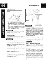
FIG. J
DO NOT
use the Wheel Dresser on the Wire
Wheel. It is for trueing abrasive wheels only.
1. Adjust tool rest (A) until it is in the flat
horizontal position as shown and 1/16” away
from the grinding wheel.
2. Turn “ON” the Bench Grinder, then turn the
Variable Speed Switch clockwise to your
desired speed setting. Let the grinding wheel
come up to a steady speed for one minute.
3. After the grinding wheel has gotten to a
steady speed, place the Wheel Dresser (B)
flat on the Tool Rest (A) with the serrated
dressing wheels facing the grinding wheel.
4. Firmly hold on to the handle of the Wheel
Dresser.
5. Move the Wheel Dresser forward until it
makes light contact with the grinding wheel
(C). After contact has been made, slide the
Wheel Dresser side to side across the Tool
Rest to dress the grinding wheel until the
edges of the grinding wheel are square
and the surface is clean.
6. After the dressing the grinding wheel, turn
“OFF” the Bench Grinder and let the grinding
wheel come to a complete stop. Allow the
grinding wheel to cool down for a period
of 10 minutes before use.
7. Inspect the grinding wheel for any irregularities
that still need to be dressed, or for and damage.
If there is damage to the wheel (cracks, major
chips missing), replace the wheel immediately.
8. The grinding wheel may now be slightly smaller
in diameter after dressing. Re-adjust the
tool rests and spark arrestors to maintain
a 1/16” clearance to the grinding wheel.
CHANGING THE GRINDING WHEEL(Fig. K)
Due to normal wear, both wheels will need to be
replaced occasionally.
1. Turn the power switch OFF and unplug the
power cord from its power source.
2. Rotate the eye shield up to access the tool rest.
3. Loosen the tool rest knob and rotate the tool
rest away from the grinding wheel.
4. Remove the Wheel Cover (B) by unscrewing
the fasteners that hold it in place.
5. Lightly push a wood wedge between the grinding
wheel and the guard to keep the shaft from turning.
Then use a crescent wrench to remove the arbor
hex nut.
FIG. K
NOTE:
The left hand arbor hex nut (E) is left
hand threaded and is loosened by rotating it
clockwise. The right hand arbor hex nut is right
hand threaded and is loosened by rotating it
counter-clockwise.
6. Remove the Outer Wheel Flange (H) and then the
abrasive wheel (I) from the arbor shaft (G).
7. The new abrasive wheel to be put onto the grinder
must have a higher R.P.M. rating than the grinder’s
motor (3,450 RPM). The new abrasive wheel must
have the correct 8” outer wheel diameter and 5/8”
bore diameter as original wheels. The labels on the
sides of the abrasive wheel must stay on.
DO NOT
remove these labels. These labels or fiber
discs help spread the holding pressure of the
tightened nuts on the grinding wheel flanges.
CAUTION
!
OPERA
TION
Содержание TDS-G200VLDB
Страница 16: ...16 BD4603 EXPLONED VIEW TDS G200VLDB...


