- 4 -
CAUTION
PLEASE READ CAREFULLY THE FOLLOWING SAFETY GUIDELINES BEFORE OPERATION.
Do not use the patio heater for indoors, as it may cause personal injury or property damage.
This outdoor heater is not intended to be installed on recreational vehicles and/or boats.
Installation and repair should be done by a qualified service person.
Improper installation, adjustment, alteration can cause personal injury or property damage.
Do not attempt to alter the unit in any manner.
Never replace or substitute the regulator with any regulator other than the factory-suggested replacement.
Do not store or use gasoline or other flammable vapors or liquids in the heater unit.
The whole gas system, hose, regulator, pilot or burner should be inspected for leaks or damage before
use, and at least annually by a qualified service person.
All leak tests should be done with a soap solution. Never use an open flame to check for leaks.
Do not use the heater until all connections have been leak tested.
Do not transport heater while it’s operating.
Do not move the heater after it has been turned off until the temperature has cooled down.
Keep the ventilation opening of the cylinder enclosure free and clear of debris.
Do not paint the radiant screen, control panel or top canopy reflector.
Control compartment, burner and circulation air passageways of the heater must be kept clean.
Frequent cleaning may be required as necessary.
The LP tank should be turned off when the heater is not in use.
Check the heater immediately if any of the following occurs:
-
The heater does not reach temperature.
-
The burner makes popping noise during use (a slight noise is normal when the burner is extinguished).
-
Smell of gas in conjunction with extreme yellow tipping of the burner flames.
The LP regulator/hose assembly must be located out of pathways where people may trip over it or in
area where the hose will not be subject to accidental damage.
Any guard or other protective device removed for servicing the heater must be replaced before operating the heater.
Adults and children should stay away from high temperature surface to avoid burns or clothing ignition.
Children should be carefully supervised when they are in the area of the heater.
Cl
To change the gas cylinder in a amply ventilated area, away from any ignition
source (candle, cigarettes, other flame producing appliances, ...);
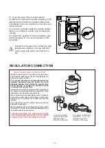
To check that the regulator seal is correctly fitted and able to fulfill its function
showed as photo right;
To not obstruct the ventilation holes of the cylinder housing;
To close the gas supply at the valve of the gas cylinder or the regulator after use;
In the event of gas leakage, the appliance shall not be used or if alight, the gas supply
shall be shut off and the appliance shall be investigated and rectified before it is used again;
To check the hose at least once per month
,
each time the cylinder is changed
,
or each time before long time no use.
If it shows signs of cracking, splitting or other deterioration it shall be exchanged for new hose of the same length and of the
equivalent quality;
The use of this appliance in enclosed areas can be dangerous and is PROHIBITED;
Read the instructions before using this appliance. The appliance must be installed in accordance with the instructions and
local regulations.
For connection of hose and regulator,and connection of regulator and hose, please refer to photo showed above.
othing or other flammable materials should not be hung on the heater or placed on or near the heater.
T
Regulator connection: tighten connection and perform another leak test. If bubbles continue appearing
should be returned to hose’s place of purchase. If leak is at Regulator/Cylinder Valve connection: disconnect,
reconnect, and perform another leak check. If you continue to see bubbles after several attempts, cylinder
valve is defective and should be returned to cylinder’s place of purchase.
urn off the gas valve immediately if smell of gas is detected. Turn Cylinder Valve OFF.If leak is at Hose/
Hose/ Regulator connection and
Regulator / Cylinder connection
seal
hose
regulater
cylinder


