– 15 –
Air to Air Heat Exchanger
Installation Manual
Air to Air Heat Exchanger
Installation Manual
10
Advanced System
WARNING
• Use wiring that meets the specifications in the Installation Manual and the stipulations in the local regulations and
laws. Use of wiring which does not meet the specifications may give rise to electric shocks, electrical leakage,
smoking and/or a fire.
• When carrying out electric connection, use the wire specified in the Installation Manual and connect and fix the wire
securely to prevent them applying external force to the terminals. Improper connection of fixing may result in fire.
• Electrical wiring work shall be conducted according to law and regulation in the community and Installation Manual.
Failure to do so may result in electrocution or short circuit.
REQUIREMENT
For the connecting procedure and electric wiring of External Input (sold separately), refer to the Installation Manual of
Remote On/Off Adapter NRB-1HE.
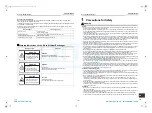
1
When the operation is linked by a signal from an external device or remotely controlled On and
Off. (Separately sold External Input)
REQUIREMENT
Do not change the setting of the Air to Air Heat Exchanger single operation for Air to Air Heat Exchangersystem linked
with air conditioners on page 19.
* Operating together if a command is sent to one of the units in the group.
* Setting for linked operation with external devices can be changed. Refer to the "Setting for linked operation with
external devices" on page 20.
•
When a remote controller is used with the Air to Air Heat Exchanger
The latter operation of the remote controller or the switch of the external device overrides the former.
(Single operation of Air to Air Heat Exchanger is possible.)
•
When no remote controller is used with the Air to Air Heat Exchanger
The operation of the Air to Air Heat Exchanger is confined to that together with the external device.
(Single operation of Air to Air Heat Exchanger is not possible.)
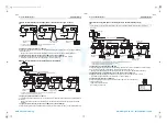
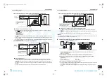
1) When the output signal of the external device is DC12V or DC24V (static signal)
• Transmission wire used to extend must be locally procured: Non-polarity, 2-core wire 0.5mm
2
Maximum length: Refer to the external device’s manual.
• Insert the Remote ON/OFF Adapter NRB-1HE (sold separately) into connector CN706 (2P).
• If a command is sent to one of the units in the group, all the air conditioners and the Air to Air Heat
Exchanger operate together.
Control circuit board of the
Air to Air Heat Exchanger
Remote ON/OFF Adapter NRB-1HE
(locally procured)
(1), (2)
DC12V
DC24V
(non polarity)
CN706
Blue (1)
Orange (2)
2m
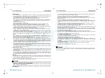
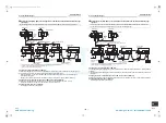
2) When the output signal of the external device is a no voltage a-contact (static signal)
• Transmission wire used to extend must be locally procured: Non-polarity, shielded wire (H05 VVC4V5-K
or 60227 IEC 74) 0.5mm
2
Maximum length: 50m
• Insert the Remote ON/OFF Adapter NRB-1HE (sold separately) into connector CN705 (5P).
• If a command is sent to one of the units in the group, all the air conditioners and the Air to Air Heat
Exchanger operate together.
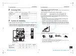
2
Operating together with a pulse transmission device such as a building management system
(separately sold External Input)
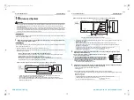
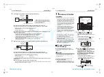
1) Select “Pulse: ON” for No.1 of SW701 (Changeover switch for pulse/
static). (Factory default: “Static”)
2) Insert the Remote ON/OFF Adapter NRB-1HE (sold separately) into
connector CN705 or CN706. (For the input signal, refer to of “1) When
the output signal of the external device is DC12V or DC24V (static
signal)” or “2) When the output signal of the external device is a no
voltage a-contact (static signal)” above.
* The pulse width should be 200msec or more.
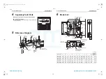
3
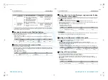
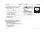
Switching the remote controller between invalid/valid, low/high, or Bypass mode/Heat exchange
mode from an external device (separately sold External Input)
* Perform connection with one of the units in the group.
* Static signal only
Insert the Remote ON/OFF Adapter NRB-1HE (sold separately) into connector CN705.
• Transmission wire used to extend must be locally procured: Non-polarity, shielded wire (H05 VVC4V5-K or
60227 IEC 74) 0.5mm
2
Maximum length: 50m
If a polar contact such as a photocoupler is used with a no
voltage a contact, connect the positive pole to terminal (5),
and the negative pole to terminal (1).
Specification of the external contact:
Contact for microcurrent
DC12V 1mA
If a polar contact such as a photocoupler is used with a no
voltage a-contact, connect the positive pole to terminal (2),
(3), or (4), and the negative pole to terminal (1).
Specification of the external contact:
Contact for microcurrent
DC12V 1mA
(locally procured)
Remote ON/OFF Adapter NRB-1HE
CN705
Control circuit board of the
Air to Air Heat Exchanger
Yellow (2)
Red (3)
White (4)
Green (1)
Black (5)
SW4
As these terminals are not used, insulate them.
Running when SW4 is closed, and stopped when it is open.
(1), (5)
No voltage
a-contact
2m
1
ON
2
SW701
ON
OFF
Changing the
pulse/static
Pulse: ON
Static: OFF
Select “ON” for No.1
of SW701
(Factory default:
Static)
29-EN
30-EN
+00ET9X463301_01EN.book Page 15 Thursday, January 20, 2011 4:41 PM
AMP Air Conditioning
www.ampair.co.uk | [email protected]


