background image

53

CONTENTS

Adjustments &

Settings

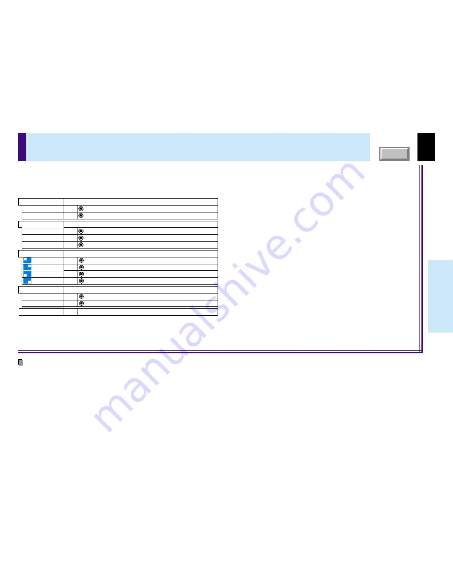
PIP menu setting

Reset

Return the settings of PIP MENU to the factory default setting.

EXEC.

Select the signal source for PIP sub-picture.

Set the PIP sub-picture size.

Source

: Video input is selected as signal source.

SET

Video

: S-Video input is selected as signal source.

SET

S-Video

Size

: The PIP sub-picture size is set to small.

SET

Small

: The PIP sub-picture size is set to medium.

SET

Middle

Select the audio input source.

Audio

: The sound of the main picture is emitted from the speaker.

SET

Main

: The sound of the sub picture is emitted from the speaker.

SET

Sub

: The PIP sub-picture size is set to large.

SET

Large

Set the PIP sub-picture display position.

Position

:The sub-picture is displayed at the upper left of the screen.

SET

:The sub-picture is displayed at the upper right of the screen.

SET

:The sub-picture is displayed at the lower left of the screen.

SET

:The sub-picture is displayed at the lower right of the screen.

SET

When a PIP sub-picture is displayed, the PIP menu screen will appear if you press the 

MENU

 button.

You can make the PIP sub-picture settings and the sound settings when a PIP subpicture is displayed.

To cancel the menu, press the 

EXIT

 button.

Notes

• The size of the PIP sub-picture differs according to the signal type (resolution) of the main picture.
• When the PIP sub-picture is turned off, the audio input source returns to the previous source (main picture).
• The settings made are memorized automatically when the power is turned off by pressing the 

ON/STANDBY

 button. If the power cord is unplugged or if a

power failure occurs while the projector is on, the settings are not memorized.

Содержание TLP-380

Страница 1: ...1 Before use CONTENTS OWNER S MANUAL 3LCD DATA PROJECTOR TLP380 TLP381 WITH DOCUMENT IMAGING CAMERA MENU TLP380 ...

Страница 2: ...ute a risk of electric shock to persons The exclamation point within an equilateral triangle is intended to alert the user to the presence of important operating and maintenance servicing instructions in the literature accompanying the appliance WARNING TO REDUCE THE RISK OF FIRE OR ELECTRIC SHOCK DO NOT EXPOSE THIS APPLIANCE TO RAIN OR MOISTURE DANGEROUS HIGH VOLTAGES ARE PRESENT INSIDE THE ENCLO...

Страница 3: ...ture may condense on the crucial internal parts To prevent the unit from possible damage do not use the unit for at least 2 hours when there is an extreme or sudden change in temperature Exemption Clauses Toshiba Corporation bears no responsibility in the case of damages arising from earthquakes fire not liable to Toshiba Corporation operating by third parties other accidents or use under abnormal...

Страница 4: ... the operating and other instructions 2 Power Sources This product should be operated only from the type of power source indicated on the marking label If you are not sure of the type of power supply to your home consult your product dealer or local power company For products intended to operate from battery power or other sources refer to the operating instructions 3 Source of Light Do not look i...

Страница 5: ...leaners Use a damp cloth for cleaning 8 Power Cord Protection Power supply cords should be routed so that they are not likely to be walked on or pinched by items placed upon or against them paying particular attention to cords at plugs convenience receptacles and the point where they exit from the product 9 Overloading Do not overload wall outlets extension cords or integral convenience receptacle...

Страница 6: ... equipment Top and bottom plates of this product develops heat and may give some undesirable damage to other unit 14 Attachments Do not use attachments not recommended by the product manufacturer as they may cause hazards 15 Accessories Do not place this product on an unstable cart stand tripod bracket or table The product may fall causing serious injury to a child or adult and serious damage to t...

Страница 7: ...maged b If liquid has been spilled or objects have fallen into the product c If the product has been exposed to rain or water d If the product does not operate normally by following the operating instructions Adjust only those controls that are covered by the operating instructions as an improper adjustment of other controls may result in damage and will often require extensive work by a qualified...

Страница 8: ...carry the projector by the camera arm Doing so can result in damage or injury 23 Do not leave documents on the unit for long periods of time while using the document imaging function Do not leave texts papers or other documents for projection on the unit for long periods of time The heat could erase the letters on a thermal paper 24 Do not move the projector while the arm is still erect Always sto...

Страница 9: ...approved by ASTA or BSI to BSI362 Always replace the fuse cover after changing the fuse If your line voltage is 220 to 240V use one of the following types of cable Plug configuration Plug type EURO 240V 10 15A UK 240V 6A Australian 240V 10A North American 240V 15A Switzerland 240V 6A Line voltage 220 240V 200 240V 200 240V 200 240V 200 240V ...

Страница 10: ...g the picture size 39 Displaying PIP Sub pictures 40 Displaying Information 41 Operating a computer by the remote control optional 42 Adjustments Settings Operating the menu screen 43 GUIDE MENU adjustments and settings 45 FULL MENU adjustments and settings Picture 46 FULL MENU adjustments Position 47 FULL MENU adjustments Color 48 FULL MENU adjustments and settings Audio 49 FULL MENU adjustments ...

Страница 11: ...hole Front side Right side Rear side Left side CAUTION Openings in the cabinet are provided for ventilation and to ensure reliable operation of the product and to protect it from overheating and these openings must not be blocked or covered The explanation here is only for the model without the document imaging camera For the model with the document imaging camera refer to 54 Note The air exhaust ...

Страница 12: ...L ADJ buttons AUTO SET button MENU button ON STANDBY button Top side Control panel To set and or adjust values on the menu To adjust the volume when the menu is not displayed To indicate the status of the projector To turn the projector on or off standby To display the menu screen and or select operations on the menu screen Use the selection buttons and the EXIT button to enlarge the image To adju...

Страница 13: ... enter audio signal from a computer or video equipment with component video output Y PB PR signal output supported 24 AUDIO L R jacks To enter audio signal from video equipment etc 24 VIDEO jack To enter video signal from video equipment etc 24 S VIDEO connector To enter S Video signal from video equipment etc 23 COMPUTER IN 2 connector To enter RGB signal from a computer etc 22 25 COMPUTER IN 1 c...

Страница 14: ...tton To freeze the picture PIP button To display the video input image as a small size picture in the computer image display window VOL ADJ buttons To set and or adjust values on the menu To adjust volume when the menu is not displayed MUTE button To cut off the picture and sound temporarily AUTO SET button ON STANDBY button Remote control transmission part To turn the projector on or off Standby ...

Страница 15: ...eries or new and old batteries When you will not be using the remote control for a prolonged period take the batteries out of the remote control When the remote control stops working or only works at very close range replace all the batteries with new ones When replacing the batteries use longer life alkaline batteries If a battery has leaked carefully wipe off any residue inside the battery case ...

Страница 16: ...mote control out of locations with excessively high temperature or humidity Do not get water on the remote control or place wet objects on it Do not disassemble the remote control Under unusual circumstances the remote control may not operate well due to the location being used or the surroundings At such times change the direction of the remote control to the projector and retry the operation Abo...

Страница 17: ...installation Floor mounted rear projection Viewing a picture projected through the back of the screen from a floor installation Viewer Translucent screen Viewer There are two ways to place the floor mounted projector Perform the Projection mode setting on the menu screen for the projection method 51 For the ceiling mounted projector placement refer to the page 21 Continued ...

Страница 18: ...0 300 Minimum At maximum zoom 1 42 2 16 2 90 3 63 5 48 7 33 11 02 Maximum At minimum zoom 1 42 1 80 2 74 3 67 4 60 6 93 9 26 a m The values are approximations 1 2 90 Point the lens straight at the center of the screen as above Determine the screen size projected on the screen The projection size depends on the distance between the lens and the screen Adjust the projection size by changing the dist...

Страница 19: ... condition before using it so it adjusts to the ambient temperature If the screen is exposed to direct sunlight or other strong light the projected picture will become too faint to see Shut out the light with curtains or by other means If the screen and the projector are not installed properly the projected picture may be distorted 3 4 Floor mounted projector placement continued Light Orange ON ST...

Страница 20: ...Release the button to lock in position 1 Turn the foot adjuster to make fine adjustment to the height Turn clockwise to lift up Turn counterclockwise to lower 2 Notes To put the foot adjuster back hold down the foot adjuster release button and lower the front slowly Be sure to hold the projector when putting the foot adjuster back so as not to let the front fall on your fingers Do not tilt the pro...

Страница 21: ...hrough the back of the screen from a ceiling installation Perform the Projection mode setting on the menu screen for the projection method 51 Note The relation between the projection size and the distance to the screen is the same as that of the floor mounted projection mode 18 Translucent screen Viewer Ceiling mounted projector placement CAUTION When a ceiling mount is required please consult wit...

Страница 22: ...er COMPUTER IN 1 connector You can project the picture from the computer Check that the power supplies for the projector and for the computer are off before connecting the cables USB COMPUTER IN 1 COMPUTER IN 2 S VIDEO VIDEO VIDEO IN R AUDIO L AUDIO IN Y PB PR MONITOR OUT CONTROL COMPUTER IN 1 connector For use as both analog RGB 1 and Y PB PR input At shipping from factory it is set for use as an...

Страница 23: ...can project the picture of analog RGB or digital RGB signal from a computer by using the COMPUTER IN 2 connector Check that the power supplies for the projector and for the computer are off before connecting the cables USB COMPUTER IN 1 COMPUTER IN 2 S VIDEO VIDEO VIDEO IN R AUDIO L AUDIO IN Y PB PR MONITOR OUT CONTROL COMPUTER IN 2 connector DVI connector For use as both analog RGB 2 input and di...

Страница 24: ... supplies for the projector and for the video equipment are off before connecting the cables USB COMPUTER IN 1 COMPUTER IN 2 S VIDEO VIDEO VIDEO IN R AUDIO L AUDIO IN Y PB PR MONITOR OUT CONTROL Pin plug red To audio output R Yellow To VIDEO jack To S VIDEO connector Be sure to connect in the proper direction To S video output AV cable supplied Pin plug white To audio output L Pin plug yellow To v...

Страница 25: ...N 1 connector For use as both analog RGB 1 and Y PB PR input At shipping from factory it is set for use as analog RGB 1 input Change the setting on the menu when using as Y PB PR input AUDIO IN jack For use as both audio signals for RGB input analog RGB 1 analog RGB 2 digital RGB and Y PB PR input Pin plug red To audio output R To AUDIO IN jack To COMPUTER IN 1 connector Be sure to connect in the ...

Страница 26: ...ROL connector To RS 232C port Control cable supplied To CONTROL connector Be sure to connect in the proper direction To remove the cover slide it up while pushing it You can control the projector by a computer connected with the control cable supplied 73 Check that the power supplies for the projector and for the computer are off before connecting the cables Note Do not connect any cable other tha...

Страница 27: ...for the projector and for the equipments are off before connecting the cables Notes The analog RGB signals or Y PB PR signals of the COMPUTER IN 1 or COMPUTER IN 2 connector selected by the input select operation are output from the MONITOR OUT connector If neither of these input sources is selected the signal of the COMPUTER IN 1 connector is output Digital RGB signals are not output Signals are ...

Страница 28: ...Green Green Green Green Green Green Flashing 1 Continued MENU ON INPUT ENTER CT 90113 KEYSTONE AUTO SET EXIT PIP FREEZE MUTE CALL RESIZE VOL ADJ STANDBY 1 K E Y S T O N E AUTO SET EXIT ON STANDBY VOL ADJ ENTER MENU I N P U T FAN TEMP LAMP ON 1 1 Indicators Remote control Control panel Main unit side ON STANDBY ON STANDBY Notes The startup screen disappears when you push the EXIT button or wait for...

Страница 29: ...age for displaying menus or messages is displayed Select a desired language At shipping from factory it is set to English Notes The language selection menu will not be displayed on the second and subsequent times you turn on the power However if Reset all 52 is executed the language selection menu will be displayed when the power is turned on next The language can also be selected on the menu scre...

Страница 30: ...VOL ADJ ENTER MENU I N P U T FAN TEMP LAMP ON INPUT INPUT INPUT INPUT ENTER ENTER Remote control Control panel Main unit side Select the input source to project There are two kinds of methods as follows 5 a and 5 b Note The types of input sources selected when the INPUT button is pressed repeatedly can be set from the menu screen 45 Continued Press INPUT and hold for two seconds The input source s...

Страница 31: ...ter used The projector projects an image by SVGA signal 800 x 600 in full screen The image quality from a computer signal other than SVGA may be inferior It is recommended to set the external monitor connected to the computer to SVGA mode 800 x 600 The projector can be also applied to DDC2B Display Data Channel 2B If your computer is applied to the DDC start up your computer after turning on the p...

Страница 32: ...ADJ to adjust volume Press the button to increase volume Press the button to decrease volume 8 VOL ADJ VOL ADJ Projection on the screen continued MENU ON INPUT ENTER CT 90113 KEYSTONE AUTO SET EXIT PIP FREEZE MUTE CALL RESIZE VOL ADJ STANDBY 8 K E Y S T O N E AUTO SET EXIT ON STANDBY VOL ADJ ENTER MENU I N P U T FAN TEMP LAMP ON 8 Remote control Control panel Main unit side About the LCD Panel The...

Страница 33: ...O SET EXIT PIP FREEZE MUTE CALL RESIZE VOL ADJ STANDBY 1 2 K E Y S T O N E AUTO SET EXIT ON STANDBY VOL ADJ ENTER MENU I N P U T FAN TEMP LAMP ON 2 1 2 Green Green Green Off Off Off Flashing Orange Orange A B C ON LAMP FAN ON LAMP FAN ON LAMP FAN Orange ON STANDBY ON STANDBY ON STANDBY ON STANDBY B C A Notes The projector consumes about 20W of power in the standby mode We recommend you unplug the ...

Страница 34: ...ency is adjusted automatically even when the AUTO SET button is not pressed Sampling phase The sampling phase is the timing at which the computer s analog RGB signals are sampled If the sampling phase is off the individual dots cannot be sampled at the proper timing resulting in blurred or flickering images Adjusting the picture automatically 1 2 MENU ON INPUT ENTER CT 90113 KEYSTONE AUTO SET EXIT...

Страница 35: ...ted This menu is the same as the sub menu which is displayed when Correct the keystone distortion of the screen is selected from GUIDE MENU 45 Press ENTER The vertical keystone distortion on the picture projected is automatically corrected The icon appears while the keystone correction is executing When the correction is finished the menu for selecting V keystone or H keystone by manual adjustment...

Страница 36: ...per and lower sides of the projected picture will be distorted 90 Select H keystone from the menu with the selection buttons and adjust the distortion of the upper and lower sides of the picture with the selection buttons 6 Press EXIT repeatedly until the menu disappears The keystone adjustment finishes EXIT EXIT Notes Due to digital correction processing some of the information may be eliminated ...

Страница 37: ... OHP etc onto the screen Note The mute mode is cancelled if another operation is performed during the mute mode MENU ON INPUT ENTER CT 90113 KEYSTONE AUTO SET EXIT PIP FREEZE MUTE CALL RESIZE VOL ADJ STANDBY MUTE MUTE Press MUTE The sound and picture are cut off temporarily To cancel the mute mode press MUTE again The image and sound will be output The icon appears in the mute mode Remote control ...

Страница 38: ...ion other than RESIZE is performed The freeze mode cannot be set when there is no input when no signals are being supplied from a signal source The input source s moving image continues to run even when the projector is set in freeze mode MENU ON INPUT ENTER CT 90113 KEYSTONE AUTO SET EXIT PIP FREEZE MUTE CALL RESIZE VOL ADJ STANDBY FREEZE FREEZE Press FREEZE The picture freezes To release the pic...

Страница 39: ...ess the EXIT button to cancel the resize mode and return to the original size MENU ON INPUT ENTER CT 90113 KEYSTONE AUTO SET EXIT PIP FREEZE MUTE CALL RESIZE VOL ADJ STANDBY EXIT RESIZE RESIZE RESIZE EXIT Notes Enlarged images can be frozen by pressing the FREEZE button The frozen image can also be enlarged or reduced The resize mode is cancelled if any operation other than setting the freeze mode...

Страница 40: ...sed when a source other than an RGB input source is selected The PIP function cannot be used without signals supplied from an RGB signal source The sub picture turns off if any other operation is performed The signal source size display position and audio input source to display sub pictures can be changed from the menu screen PIP Displaying PIP Sub pictures MENU ON INPUT ENTER CT 90113 KEYSTONE A...

Страница 41: ...VOL ADJ STANDBY CALL Displaying Information Information on the input signal source etc can be displayed Remote control Press CALL The information described below is displayed The information display turns off when the CALL button is pressed again Status display Input current input source H resolution the horizontal resolution of the input signal at RGB input V resolution the vertical resolution of...

Страница 42: ... AUTO SET EXIT PIP FREEZE MUTE CALL RESIZE VOLUME ADJUST LASER MENU ON STANDBY INPUT L CLICK R CLICK ENTER KEYSTONE AUTO SET EXIT PIP FREEZE MUTE CALL RESIZE VOLUME ADJUST LASER USB COMPUTER IN 1 COMPUTER IN 2 S VIDEO VIDEO VIDEO IN R AUDIO L AUDIO IN Y PB PR MONITOR OUT CONTROL R CLICK L CLICK To USB connector Be sure to connect in the proper direction Pointer control USB cable Not supplied To US...

Страница 43: ...NU has seven pages of Picture Position Color Audio Display Default setting and Reset Use the selection button to change the page of FULL MENU Picture Position Color Default setting Reset Display Audio Select the item with the selection button Press ENTER to confirm The item selected can be adjusted or set Press EXIT and return When you select other items press EXIT repeatedly until GUIDE MENU appe...

Страница 44: ...the small list of the selected adjusting items is displayed This is useful as you can see a main picture not hidden under FULL MENU Adjust with VOL ADJ or selection buttons Press EXIT FULL MENU is displayed and you can select other items Press EXIT FULL MENU disappears and adjustment or setting is finished Method 1 Method 2 Adjust with VOL ADJ Press the selection button when selecting other items ...

Страница 45: ...color depth of the picture ADJ Adjust the sensitivity of the document imaging camera Camera gain Adjust the document imaging camera s gain ADJ Yes Yes Yes common for all of the inputs Yes common for all of the inputs Digital RGB Y PB PR Video The relationship between input source and item Yes Adjustable Not displayed S Video Camera AnalogRGB 1 AnalogRGB 2 Select a shutter speed below to decrease t...

Страница 46: ...125i The Y PB PR signal format is fixed to 1125i mode SET Shutter Auto The shutter speed is set automatically SET 50Hz The shutter speed is fixed at 50 Hz SET 60Hz The shutter speed is fixed at 60 Hz SET Screen size Full The picture is converted to SVGA 800 x 600 dot resolution SET Thru The picture is displayed with the input source resolution SET Wide The picture is converted to wide screen forma...

Страница 47: ... Yes Yes Yes Yes Yes Yes Yes Yes Yes Digital RGB Y PB PR Video The relationship between input source and item Yes Adjustable Not displayed S Video Camera AnalogRGB 1 AnalogRGB 2 You can adjust the picture position etc of the analog RGB input from FULL MENU Position To operate FULL MENU refer to page 44 Notes This menu is not displayed except with analog RGB input The adjustment of each item in thi...

Страница 48: ... EXEC Yes Yes Yes Yes Yes Yes Yes Yes Yes Yes Yes Yes Yes Yes Yes Yes Yes Yes Yes Yes Yes Yes Yes Yes Yes Yes Yes Yes Yes Yes Yes Yes Yes Digital RGB Y PB PR Video The relationship between input source and item Yes Adjustable Not displayed S Video Camera AnalogRGB 1 AnalogRGB 2 You can adjust the color condition of the picture from FULL MENU Color To operate FULL MENU refer to page 44 Note The adj...

Страница 49: ...he speaker SET R Only the sound of the right channel is emitted from the speaker SET Yes Yes Yes Yes Yes Yes Digital RGB Y PB PR Video The relationship between input source and item Yes Adjustable Not displayed S Video Camera AnalogRGB 1 AnalogRGB 2 You can set the sound emitted from the speaker from FULL MENU Audio To operate FULL MENU refer to page 44 Notes When the camera input is selected soun...

Страница 50: ...ET Menu position Upper left Upper right The menu is displayed at the upper left of the screen SET The menu is displayed at the upper right of the screen SET Lower left The menu is displayed at the lower left of the screen SET Lower right The menu is displayed at the lower right of the screen SET Yes common for all of the inputs Yes common for all of the inputs Yes common for all of the inputs Yes ...

Страница 51: ... of the inputs Power on Manual The power turns on by pressing the ON STANDBY button SET Auto When the power plug is inserted the power is on SET Yes common for all of the inputs Start up screen On The start up display appears when the power is turned on SET Off The start up display does not appear when the power is turned on SET Yes common for all of the inputs Yes common for all of the inputs Dig...

Страница 52: ...epending on the using environment if the projector is subject to vibrations or shock etc the standard may change If the keystone distortion is not corrected properly when Auto V keystone 35 is executed with the screen installed vertically put the projector s foot adjuster back 20 and set the projector on a flat surface then execute Horizontal reference value reset function Notes If the projector s...

Страница 53: ...layed at the upper left of the screen SET The sub picture is displayed at the upper right of the screen SET The sub picture is displayed at the lower left of the screen SET The sub picture is displayed at the lower right of the screen SET When a PIP sub picture is displayed the PIP menu screen will appear if you press the MENU button You can make the PIP sub picture settings and the sound settings...

Страница 54: ...57 58 16 Arm Camera head Camera lens LED light Focusing ring Camera control panel CAMERA GAIN buttons To adjust the camera gain LOCK W BALANCE indicator Lights when the white balance is locked W BALANCE button To switch white balance settings between automatic adjustment and lock CAMERA button To select the camera source Press again to return to the previous input source OVERLAY button To turn on ...

Страница 55: ...the back of the projector and set the arm and camera head over them Preparation of the document imaging camera 1 Raise up the arm Before preparations stowed away 2 Extend the arm 3 Turn the arm 4 Open the camera head 5 Turn the camera head 6 Pull up the light 7 Turn the light STORE CAMER A ARM LIGHT LOCK W BALA NCE GAIN FOCU S STORE CAMER A ARM LIGHT LOCK W BALA NCE GAIN STORE CAMER A ARM LIGHT LO...

Страница 56: ...t illustrations etc onto or around the projector and turn the camera head to the direction of the document 2 123 123 123 123 FOCUS FOCUS STORE CAMERA ARM LIGHT LOCK W BALANC E GAIN FO CU S 123 123 STORE CAMERA ARM LIGHT LOCK W BALANC E GAIN FO CU S Continued Images on the screen Setting direction You can also place the materials at the back of the projector and move the arm and the camera head ove...

Страница 57: ...amera s picture 3 Continued CAMERA INPUT INPUT K E Y S T O N E AUTO SET EXIT ON STANDBY VOL ADJ ENTER MENU I N P U T FAN TEMP LAMP ON 3 3 OVERLAY CAMERA ARM LIGHT LOCK W BALANCE CAMERA GAIN MENU ON INPUT ENTER CT 90113 KEYSTONE AUTO SET EXIT PIP FREEZE MUTE CALL RESIZE VOL ADJ STANDBY 3 Picture projection with the document imaging camera continued Move the camera head to adjust the size of the pic...

Страница 58: ...ERA GAIN 6 Picture projection with the document imaging camera continued When finished turn off the light and close it and put back the arm Follow the steps of Preparation of the document imaging camera in reverse 7 Notes Though this projector uses a 1 45 million pixel camera unit the images projected on the screen are 800 x 600 dot images If the Screen size in the menu screen 46 is set to Full th...

Страница 59: ...urface and set the camera so that the paper is projected onto the screen Adjust the camera to make the white paper be projected on the wholescreen 1 STORE CAMERA ARM LIGHT LOCK W BALANCE GAIN FOC US Select the input source using the overlay function by pressing INPUT Select an input source other than the camera input 2 INPUT INPUT Press OVERLAY 3 OVERLAY Draw any line on the paper with a red or bl...

Страница 60: ...This is not a malfunction If you put the arm back and raise it again while the white balance is locked the LOCK indicator is lit the projector will release the white balance Depending on the tint of the indoor illumination the white balance might not be compensated optimally Should this be the case or if you would like to adjust it to a desired tint adjust R level G level or B level on the FULL ME...

Страница 61: ...T K E Y S T O N E AUTO SET EXIT ON STANDBY VOL ADJ ENTER MENU I N P U T FAN TEMP LAMP ON 2 OVERLAY CAMERA ARM LIGHT LOCK W BALANCE CAMERA GAIN F O C U S Press ARM LIGHT on the camera control panel and EXIT on the projector s control panel simultaneously You can not use the remote control buttons 2 Camera control panel Control panel Main unit side Press both sides Camera lens For the CCD image sens...

Страница 62: ...y so the intake and exhaust fan s holes are not covered Turn the projector off and leave it for a while and turn it on again Clean the air filter The icon appears before the power turned off The projector returns to the standby mode after the fault display has been shown for about 2 minutes The power turns off or does not come on Trouble with the cooling fan Unplug the power cord and call the deal...

Страница 63: ...tely 2 1 Unplug the power cord Take off the air filter cover The filter is on the right side of the projector Pull the bottom side of the cover upward to remove the filter cover Detach the air filter Detach the air filter from the air filter cover The air filter cover air filter and filter frame can be disassembled Cleaner s nozzle Clean the air filter Use a vacuum cleaner to carefully remove any ...

Страница 64: ... air filter is dusty the ventilation is impaired This causes the temperature inside the projector to rise and may damage the unit Attach the air filter cover firmly after the cleaning If it is not set correctly the dusts will enter and they will be projected and overlapped on the picture If you wash the air filter with water be sure to let it dry fully before reinstalling it Using it damp will res...

Страница 65: ...f stains from the surface To remove difficult stains use a soft cloth slightly moistened with a weak solution of synthetic detergent and water and finish with a soft dry cloth Replacing the intake exhaust fans and air filter To maintain the efficiency of the projector replace the intake and exhaust fans about every two to three years Ask the dealer for the replacement CAUTION If you use the projec...

Страница 66: ...ately For details refer to the lamp instruction If you have been using the projector the lamp will be very hot and may cause burn injuries Wait for the lamp to cool for longer than 1 hour before replacing it If the lamp should break please handle with care to avoid injury due to broken pieces and contact your dealer for repair service Unplug the power cord 1 Wait until the lamp gets cool enough 2 ...

Страница 67: ...the power will not turn on Use a new lamp when replacing it The lamp is made of glass and is very fragile Do not touch the lamp with your bare hands and do not jolt or damage it Do not try to use an exhausted lamp A small amount of inorganic mercury harmful to environment is used for the lamp Dispose of the exhausted lamp according to the rules of your area Lamp replacement continued 5 Load a new ...

Страница 68: ...e is out of focus The projection distance is not appropriate The projecting light is not hitting the screen squarely The Brightness Contrast Sharpness or Phase adjustments are not correct The Brightness or Contrast adjustments are not correct The lamp life is ending Correction Firmly plug in the power cord Attach the cover correctly Lower the ambient temperature of the projection room and turn the...

Страница 69: ...perly connected The computer or OS is not compatible The batteries are exhausted The lens is dirty The picture is out of focus The light is not on Image is being affected by fluorescent light in the room The image s number of frames is low This is not a malfunction The image s number of frames is low This is not a malfunction Correction Make the Picture adjustments Replace the lamp Face the remote...

Страница 70: ...gnal Analog R G B signal 0 7V p p 75Ω Horizontal sync signal TTL level positive negative polarity Vertical sync signal TTL level positive negative polarity Pin No 1 2 3 4 5 6 7 8 9 10 11 12 13 14 15 RGB input Video signal Red Video signal Green Video signal Blue GND GND GND Red GND Green GND Blue N C GND GND DDC data Horizontal sync signal Vertical sync signal DDC clock Y PB PR input Color differe...

Страница 71: ... 666 SVGA75 800 x 600 160 800 16 80 1056 46 875 75 000 49 500 21 600 1 3 625 SVGA85 800 x 600 152 800 32 64 1048 53 674 85 061 56 250 27 600 1 3 631 MAC16 832 x 624 216 832 40 64 1152 49 725 74 550 57 283 39 632 1 3 667 XGA43i 1024 x 768 56 1024 8 176 1264 35 522 43 479 44 900 20 768 0 4 817 XGA60 1024 x 768 160 1024 24 136 1344 48 363 60 004 65 000 29 768 3 6 806 XGA70 1024 x 768 144 1024 24 136 ...

Страница 72: ...2 2160 87 500 70 000 189 000 46 1200 1 3 1250 UXGA75 1600 x 1200 304 1600 64 192 2160 93 750 75 000 202 500 46 1200 1 3 1250 Mode Resolution A Pixels B Pixels C Pixels D Pixels E Pixels fh kHz fv Hz Clock MHz G Lines H Lines I Lines J Lines K Lines Notes Signal sources marked are displayed in compressed format so some of their data may be missing or their picture quality may be degraded With analo...

Страница 73: ...6 7 8 Notes When commands are transmitted serially wait for the reply of the projector acknowledge or not acknowledge before sending the next command Adjustment commands include ARG increase adjustment value and ALF decrease adjustment value For usable items marked Yes send after the selection command The Yes marks in the input source columns indicate that that command can be used 7 8 6 3 4 5 1 2 ...

Страница 74: ...s PAL KV2 Yes SECAM KV3 Yes PAL N KV4 Yes PAL M KV5 Yes PAL60 KV6 Yes NTSC4 43 KV7 Yes Signal format Auto SG0 Yes 525i SG1 Yes 525p SG2 Yes 625i SG3 Yes 750p SG4 Yes 1125i SG5 Yes Shutter Auto CSA Yes 50Hz CS0 Yes 60Hz CS1 Yes Screen size Full MSF Yes Yes Yes Yes Yes Thru MST Yes Yes Yes Yes Yes Wide MSW Yes Yes Picture reset DRV Yes Yes Yes Yes Yes Position H position PHP Yes Yes V position PVP Y...

Страница 75: ... select RCA L R APA Yes L APL Yes R APR Yes Loudness RCA Off LR0 Yes On LR1 Yes Channel select Mini L R AMA Yes Yes Yes L AML Yes Yes Yes R AMR Yes Yes Yes Loudness Mini Off LM0 Yes Yes Yes On LM1 Yes Yes Yes Audio reset DRA Yes Yes Yes Yes Display V keystone PKV Yes Yes Yes Yes Yes Yes H keystone PKH Yes Yes Yes Yes Yes Yes Keystone reset DRK Yes Yes Yes Yes Yes Language English LEN Yes Yes Yes Y...

Страница 76: ...Yes Yes Yes Yes Analog RGB 1 IS0 Yes Yes Yes Yes Yes Y PB PR IS1 Yes Yes Yes Yes Yes COMPUTER IN 2 On I20 Yes Yes Yes Yes Yes Off I21 Yes Yes Yes Yes Yes Analog RGB 2 IV0 Yes Yes Yes Yes Yes Digital RGB IV1 Yes Yes Yes Yes Yes VIDEO On I30 Yes Yes Yes Yes Yes Off I31 Yes Yes Yes Yes Yes S VIDEO On I40 Yes Yes Yes Yes Yes Off I41 Yes Yes Yes Yes Yes CAMERA On I60 Yes Yes Yes Yes Yes Off I61 Yes Yes...

Страница 77: ... VIDEO IN3 Yes Yes Yes Yes Yes S VIDEO IN4 Yes Yes Yes Yes Yes CAMERA IN6 Yes Yes Yes Yes Yes RESIZE Increase the enlargement ratio RUP Yes Yes Yes Yes Yes Decrease the enlargement ratio Minimum reset status RDW Yes Yes Yes Yes Yes Move the enlargement section Up PO1 Yes Yes Yes Yes Yes Down PO2 Yes Yes Yes Yes Yes Left PO3 Yes Yes Yes Yes Yes Right PO4 Yes Yes Yes Yes Yes Enlargement reset RS0 Ye...

Страница 78: ...log RGB 2 S Video PIP PIP audio source Main PA0 Yes Yes Continued Sub PA1 Yes Yes PIP reset DRW Yes Yes AUTO SET PAT Yes Yes Auto V keystone PKA Yes Yes Yes Yes Yes Overlay On CON Yes Yes Yes Yes Off COF Yes Yes Yes Yes Camera Shortcut CDR Yes Yes Yes Yes Yes Auto W B On CW1 Yes Yes Yes Yes Yes Off CW0 Yes Yes Yes Yes Yes Lighting On CL1 Yes Yes Yes Yes Yes Off CL0 Yes Yes Yes Yes Yes ...

Страница 79: ...tion MONITOR OUT Mini D sub 15 pin Analog RGB Y PB PR combination S VIDEO IN Mini DIN 4 pin VIDEO IN 1V p p 75Ω RCA pin jack AUDIO L R IN 1 3V rms more than 22kΩ RCA pin jack x 2 AUDIO IN 1 3V rms more than 22kΩ ø3 5mm stereo mini jack CONTROL Mini DIN 8 pin RS 232C USB Type B Continued Liquid crystal display Projection system 3 panel transmission Panel size 0 9 inches Driving system TFT active ma...

Страница 80: ...EC Corporation VGA SVGA XGA SXGA UXGA are trademarks or registered trademarks of International Business Machines Corporation Macintosh is a registered trademark of Apple Computer Inc Windows is a registered trademark of Microsoft Corporation in the U S and other countries Display Data Channel is a trademark of Video Electronics Standard Association Specifications continued ...

Отзывы: