background image

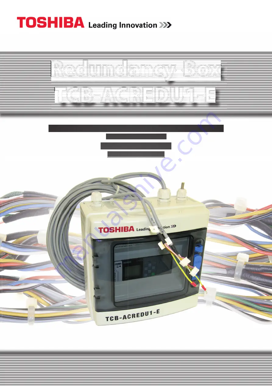
Redundancy-Box

TCB-ACREDU1-E

AIR-COND Klimaanlagen-Handelsgesellschaft m.b.H.

Haushamer Straße 2

A-8054 Graz-Seiersberg

www.air-cond.com

Содержание TCB-ACREDU1-E

Страница 1: ...1 E TCB ACREDU1 E TCB ACREDU1 E TCB ACREDU1 E TCB ACREDU1 E TCB ACREDU1 E TCB ACREDU1 E TCB ACREDU1 E TCB ACREDU1 E TCB ACREDU1 E TCB ACREDU1 E TCB ACREDU1 E TCB ACREDU1 E TCB ACREDU1 E TCB ACREDU1 E TCB ACREDU1 E TCB ACREDU1 E TCB ACREDU1 E TCB ACREDU1 E TCB ACREDU1 E TCB ACREDU1 E TCB ACREDU1 E TCB ACREDU1 E TCB ACREDU1 E TCB ACREDU1 E TCB ACREDU1 E TCB ACREDU1 E TCB ACREDU1 E TCB ACREDU1 E TCB ...

Страница 2: ...2 I TOSHIBA VERSION E ...

Страница 3: ...10 6 2 SWITCHING ON THE REDUNDANCY BOX 10 7 MAINTENANCE 11 8 OPERATION 12 8 1 GENERAL 12 8 2 PASSWORD LEVEL 13 8 3 TO SWITCH FROM OPERATOR TO ADMINISTRATOR 14 8 4 TO SWITCH FROM ADMINISTRATOR TO OPERATOR 15 8 5 START SCREEN 16 8 6 MAIN IMAGE 16 8 7 OPERATION HOURS SWITCHOVER 17 8 8 TEMPERATURE STAGE FUNCTION 17 8 9 TEMPERATURE ALARM 18 8 10 OPERATION HOURS RESET 18 8 11 SENSOR MONITORING 19 8 12 C...

Страница 4: ...termine voltage Earth and short circuit Cover or shield any adjacent live parts DANGER Hazardous voltage Will cause death or serious injury Commissioning and operation of a unit system may only be performed by qualified personnel Qualified personnel within the meaning of the safety notices of this documentation are persons who are authorized to take equipment systems and circuits in accordance wit...

Страница 5: ...is referred to in the electrical equipment and disconnect from live parts All pole disconnection can be achieved by for example Turn off the circuit breaker Turn off the motor protection switch Unscrewing fuses Dragging NH fuses 2 In order to ensure that the branch remains unlocked during the work it must be secured against accidental reconnection This can be achieved by e g the motor and system p...

Страница 6: ...6 I TOSHIBA 3 Identification 3 1 Unit designation The Toshiba Redundancy Box TCB ACREDU1 E is a compact control unit and is shipped as a unit 3 2 Nameplate ...

Страница 7: ... control system All relevant operating parameters can be set and activated via the menu on the controller display 4 2 Delivery The factory setting of Redundancy box is wired with the two control lines each 8 m for unit 1 and unit 2 finished internally The control lines are provided with CN 61 plugs for connection to the respective indoor unit Also a temperature sensor PT100 with 3 m cable length i...

Страница 8: ...e place in the areas of 40 C to 50 C 5 1 Voltage The control voltage of the indoor units 1 and 2 is 12VDC and is decoupled via relay terminal Feed 230VAC Internal Control Voltage 24VDC Enable contact externally 24VDC Control voltage indoor units 12VDC CN61 connector 5 2 Clamping points The terminals for the feed and the release contact are externally labeled as the wiring diagram Both relay output...

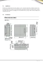
Страница 9: ...2 and at the end fixed connector D1 a polarized electrical connection is ensured Both lines are marked as follows U1 stands for unit 1 and U2 is for unit 2 The connectors are plugged into the motherboard on contact CN61 and the shielding line is attached on the unit 5 4 Dimensions Dimensions mm ...

Страница 10: ...r damage and pollution Open locking device 6 2 Switching on the Redundancy box When all installation inspections were successfully carried out switch on the supply voltage and measure them The supply voltage should be 230 VAC Only after that close the locking device and the unit is ready for operation After switching on the control goes through internal functions After a successful start the splas...

Страница 11: ...e contactors and relays these should be checked annually Whenever possible malfunctions are displayed by the display Defective parts must be replaced by qualified personnel in compliance with the applicab le safety regulations CAUTION All maintenance and inspection work on the Redundancy box may only be carried out by qualified and trained personnel in compliance with the statutory safety regulati...

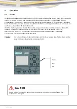
Страница 12: ... can use from a conventional PC or a mobile unit With this method you access to the PLC control using an Internet connected unit conventional PC tablet or smartphone with Web browser function This works on the IP address of the PLC Make sure that your PC or mobile unit is connected to the desired Redundancy box safely The web user access is configured and activated Display It is a monochrome displ...

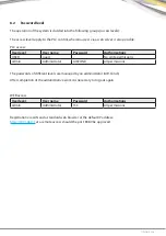
Страница 13: ...R guest No write permissions Admin Administrator AIRCOND All permissions The passwords of different levels are managed by an administrator AIR Cond After completion of the administrative work it is necessary to log out again WEB access User level User name Password Authorizations Admin Administrator TCC All permissions Registration via LAN and a standard web browser at the default IP address http ...

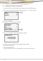
Страница 14: ...Take over Button OK 3 Move cursor to Cursor button UP or DOWN 4 Take over Click OK to confirm The display appears as follows 5 Pressing cursor keys to navigate through the alphabet and select letters current Password AIRCOND 6 Confirm password Button OK The control switches now to access level Administrator and returns to the main menu Setup Network Diagnosis Message config Home Screen LCD Menu La...

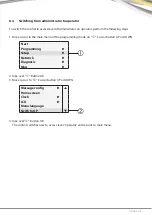
Страница 15: ... 1 Move cursor in the main menu of the programming mode on Cursor button UP or DOWN 2 Take over Button OK 3 Move cursor to Cursor button UP or DOWN 4 Take over Button OK The control switches now to access level operator and returns to main menu Start Programming Setup Network Diagnosis Map Message config Home screen Clock LCD Menu language Swith to OP ...

Страница 16: ...t and then jumps directly to the start screen 8 6 Main image At the main image you haves an overview of the system and at the same time all the relevant information of the two indoor units ie status and equipment mode This page is without control panels OFF Unit is switched off RUN Unit in operation STATUS OK Unit has no errors STATUS FAULT Unit has an error light blinks red Version OK FAULT RUN O...

Страница 17: ...e modified value must be confirmed with OK Leaving from the input function is performed by pressing the ESC key Thus the inputs are activated 8 8 Temperature stage function With this image the parameters of the temperature dependent switch and the release are defined By Function On Off this switching can be enabled disabled At higher or lower temperature the second indoor unit is connected or disc...

Страница 18: ...ection 8 7 At fault both contacts Q3 Q4 flash each with 1 Hz U1 and U2 remain in operation 8 10 Operation hours Reset The reset of the operating hours takes place in this image Air conditioning unit U1 and U2 can be opera ted separately After a reset the counter value is set to 0 and the operation hour counting begins anew The procedure to carry out changes has been described in section 8 7 Setpoi...

Страница 19: ...onitoring The temperature sensor PT100 is once it is activated by the function 8 7 and 8 10 monitored against short circuit and wire break The alarm is displayed in the alarm box At fault both contacts Q3 Q4 flash each with 1 Hz ...

Страница 20: ...OK key you arrive at the inquiry Stop program YES NO which you confirm with YES This allows you to change the network parameters The control provides a menu command to configure the network settings 1 Turn the control to the programming mode stop and YES 2 Move the cursor to 3 Press OK to confirm 4 Move the cursor to 5 Press OK to confirm 6 The display shows only the default IP address of your con...

Страница 21: ...change the setting press OK When the cursor appears as a flashing solid square move it with the up and down arrow button on the position of the number to be changed and to increase or decrease them To confirm your changes press OK 8 Proceed with the up and down arrow button to set the gateway address The default gateway is displayed as shown above To change the setting press OK When the cursor app...

Страница 22: ...echnician 8 14 Registration Over the registration you get to the system information and further to the respective sub menus 1 Open your web browser 2 Enter the IP address of your controller in the IP Address Bar LAN access Local Area Network via 192 168 0 1 Remote access via 192 168 0 1 8080 Note Make sure that TCP Port 8080 is selected for remote access Network connection RJ45 ...

Страница 23: ...ng history and passwords are stored The access to a single base module can take place simultaneously across several web server clients Due to the memory load this may also affect the performance of the associated base module 8 15 View system information Once logged in the web server displays all the system information of your base module such as module generation module type firmware FW version IP...

Страница 24: ...grammed cursor or function key click or tap on the ESC key again To disable the display of an active message while this message has been previously configured in Soft Comfort as acknowledged click or tap the OK button 8 17 View and edit variable memory tables With the Web server you can check and change variable storage tables in a web browser Click or tap on the navigation bar on the left to disp...

Страница 25: ...E U2 CANGEOVER FUNCTION ON OFF HOURS LEFT VALUE h VALUE h TEMPERATURE FUNCTION ON OFF ACTUAL VALUE C ON VALUE C OFF VALUE C TEMP ALARM FUNCTION ON OFF SETPOINT VALUE C ACTUAL VALUE C U1 RUNHOURS U2 VALUE h VALUE h RESETHOURS ON OFF ON OFF Date and Time ANALOG INPUTS ANALOG OUTPUTS OUTPUTS INPUTS FLAGS ESC C Main menu start page ...

Страница 26: ...26 I TOSHIBA ...

Страница 27: ...TOSHIBA I 27 8 19 Circuit diagram ...

Страница 28: ...28 I TOSHIBA 8 20 Declaration of conformity ...

Страница 29: ...pdated topsheet labeling and contents AIR COND Rudolf Bayer 29 10 2015 B Updated network WEB and contents AIR COND Rudolf Bayer 16 11 2015 C Updated navigation menu AIR COND Rudolf Bayer 15 12 2015 D Software update to version 1 3 AIR COND Rudolf Bayer 17 02 2016 E Software update to version 1 4 AIR COND ...

Страница 30: ...30 I TOSHIBA ...

Страница 31: ...TOSHIBA I 31 ...

Страница 32: ...AIR COND Klimaanlagen Handelsgesellschaft m b H Haushamer Straße 2 A 8054 Graz Seiersberg www air cond com ...

Отзывы: