IF08CZ10 April, 2019
- 35 -
INTERFACE (cont’d)
Digital Output
There are 10 programmable digital outputs (DO1-10). DO1-4 are photo-coupler outputs and must
be used with 24Vdc. DO1-3 may be connected to an external 24V supply if desired. DO4 is connected the
drive internal 24V supply. The other 6 outputs (DO5-10) are form C relay outputs. These relays can be
programmed to any bit in any word in the drive. The most commonly used bits can be found in the
SSEQ_OUT1-4 words. The word assignment is made via DO1_AS – DO10_AS parameters.
Analog Input
The drive has three general-purpose analog inputs (AIN1-3). They can be configured to any variable in the
drive through assignment of AINn_AS (where n = 1 to 3 ).
As a general-purpose analog input, the standard I/O circuit brd. (XIO) has one general-purpose analog input
(AIN1). Expanded I/O brd. (EXIO) has two additional inputs (AIN2 and AIN3). AIN1 has an option for
current input thru an internal resistor, but AIN2 and 3 are voltage input only.
Each analog input signal is converted to the digital value through a 12-bit A/D converter. A
±
10 Vdc input is
converted to counts by software and is stored in the target data register. Since this signal is directly
connected to the control circuit, it is recommended that an isolation transducer be used. The data register,
the gain and the offset are set with the following parameters:
AIN#_AS
Target register – set by symbol name
AIN#_GS
Gain setting – defines the number of counts for 10V input
AIN#_OS
Offset setting – offsets the input
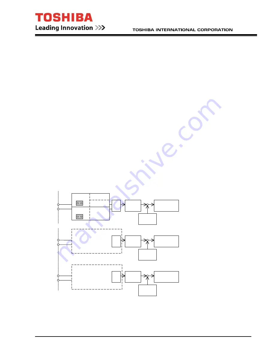
The "#" of each parameter name denotes the AD channel number. The following figure shows the input circuit:
TB2-1
TB2-2
AIN1_TYPE=0
20V
JP1B
AIN1_TYPE=2
4-20mA
JP1A
AIN1
Gain
AIN1_GS
Data destination
AIN1_AS
+
+
Offset
AIN1_OS
XIO, ARND-4045
TB2-19
TB2-20
AIN2
Gain
AIN2_GS
Data destination
AIN2_AS
+
+
Offset
AIN2_OS
Input
Input
TB2-21
TB2-22
AIN3
Gain
AIN3_GS
Data destination
AIN3_AS
+
Offset
AIN3_OS
10V Voltage input only
10V Voltage input only
+
AIN1_TYPE=1
10V
+/-10V
4-20mA
EXIF, PC61910P206A
Analog Input Circuit
Содержание T300MTX
Страница 19: ...IF08CZ10 April 2019 xix This page intentionally left blank ...
Страница 61: ...IF08CZ10 April 2019 39 CIRCUIT OPERATION cont d 4160V configuration Non regen 4160V configuration Regen ...
Страница 62: ...IF08CZ10 April 2019 40 CIRCUIT OPERATION cont d 6600V configuration ...
Страница 78: ...IF08CZ10 April 2019 56 DRIVE INSTALLATION DRAWINGS Frame 0 drive lifting and assembly ...
Страница 97: ...IF08CZ10 April 2019 75 DRIVE INSTALLATION DRAWINGS cont d Frame G4P drive lifting and assembly ...
Страница 98: ...IF08CZ10 April 2019 76 DRIVE INSTALLATION DRAWINGS cont d Frame G4P drive main cable installation ...
Страница 99: ...IF08CZ10 April 2019 77 DRIVE INSTALLATION DRAWINGS cont d Frame G4P module lifting and installation D C B A ...
Страница 101: ...IF08CZ10 April 2019 79 DRIVE INSTALLATION DRAWINGS cont d Frame H4P drive lifting and assembly ...
Страница 102: ...IF08CZ10 April 2019 80 DRIVE INSTALLATION DRAWINGS cont d Frame H4P drive main cable installation ...
Страница 103: ...IF08CZ10 April 2019 81 DRIVE INSTALLATION DRAWINGS cont d Frame H4P module lifting and installation ...
Страница 106: ...IF08CZ10 April 2019 84 DRIVE INSTALLATION DRAWINGS cont d Frame A2 drive lifting and assembly ...
Страница 109: ...IF08CZ10 April 2019 87 DRIVE INSTALLATION DRAWINGS cont d Frame B2 drive lifting and assembly ...
Страница 111: ...IF08CZ10 April 2019 89 DRIVE INSTALLATION DRAWINGS cont d Frame D2 drive lifting and assembly ...
Страница 112: ...IF08CZ10 April 2019 90 DRIVE INSTALLATION DRAWINGS cont d Frame D2 drive main terminal locations ...
Страница 114: ...IF08CZ10 April 2019 92 DRIVE INSTALLATION DRAWINGS cont d Frame A4µ drive lifting and assembly ...
Страница 116: ...IF08CZ10 April 2019 94 DRIVE INSTALLATION DRAWINGS cont d Frame A4 drive lifting and assembly ...
Страница 118: ...IF08CZ10 April 2019 96 DRIVE INSTALLATION DRAWINGS cont d Frame B4 drive lifting and installation ...
Страница 120: ...IF08CZ10 April 2019 98 DRIVE INSTALLATION DRAWINGS cont d Frame B6S drive lifting and assembly ...
Страница 121: ...IF08CZ10 April 2019 99 DRIVE INSTALLATION DRAWINGS cont d Frame B6S drive main terminal locations ...
Страница 123: ...IF08CZ10 April 2019 101 DRIVE INSTALLATION DRAWINGS cont d Frame C6S drive lifting and assembly ...
Страница 124: ...IF08CZ10 April 2019 102 DRIVE INSTALLATION DRAWINGS cont d Frame C6S drive main terminal locations ...
Страница 125: ...IF08CZ10 April 2019 103 DRIVE INSTALLATION DRAWINGS cont d Frame D6S module lifting and installation ...
Страница 126: ...IF08CZ10 April 2019 104 DRIVE INSTALLATION DRAWINGS cont d Frame D6S drive lifting and assembly ...
Страница 127: ...IF08CZ10 April 2019 105 DRIVE INSTALLATION DRAWINGS cont d Frame D6S drive main terminal locations ...
Страница 128: ...IF08CZ10 April 2019 106 DRIVE INSTALLATION DRAWINGS cont d Frame F6S F6S module lifting and installation ...
Страница 129: ...IF08CZ10 April 2019 107 DRIVE INSTALLATION DRAWINGS cont d Frame F6S drive lifting and assembly ...
Страница 130: ...IF08CZ10 April 2019 108 DRIVE INSTALLATION DRAWINGS cont d Frame F6S drive lifting and assembly ...
Страница 131: ...IF08CZ10 April 2019 109 DRIVE INSTALLATION DRAWINGS cont d Frame F6S F6S drive main terminal locations ...
Страница 132: ...IF08CZ10 April 2019 110 DRIVE INSTALLATION DRAWINGS cont d Frame MTX 15 drive lifting and assembly ...
Страница 133: ...IF08CZ10 April 2019 111 DRIVE INSTALLATION DRAWINGS cont d Frame MTX 30 drive lifting and assembly ...
Страница 135: ...IF08CZ10 April 2019 113 DRIVE INSTALLATION DRAWINGS cont d Frame MTX2 15 drive lifting and assembly ...
Страница 137: ...IF08CZ10 April 2019 115 DRIVE INSTALLATION DRAWINGS cont d Frame A4R drive lifting and assembly ...
Страница 139: ...IF08CZ10 April 2019 117 DRIVE INSTALLATION DRAWINGS cont d Frame B4R drive lifting and assembly ...


