⎯
100
⎯
6 F 2 S 0 7 1 5
1.6
Creating Line Element and Zero-
Phase Element
This section describes how to create new line element and zero-phase element form the
selected analog elements.
《
Note for Operation
》
●
You can created line elements and zero-phase elements from the following elements:
Va
・
Vb
→
Vab Ia
・
Ib
→
Iab
Vb
・
Vc
→
Vbc Ib
・
Ic
→
Ibc
Vc
・
Va
→
Vca Ic
・
Ia
→
Ica
Va
・
Vb
・
Vc
→
Vo Ia
・
Ib
・
Ic
→
Io
●
When you create a zero-phase element, it is registered in the phase order setting
processed internally.
(The created zero-phase element is used for the analysis calculation.)
《
Operating Procedure
》
①
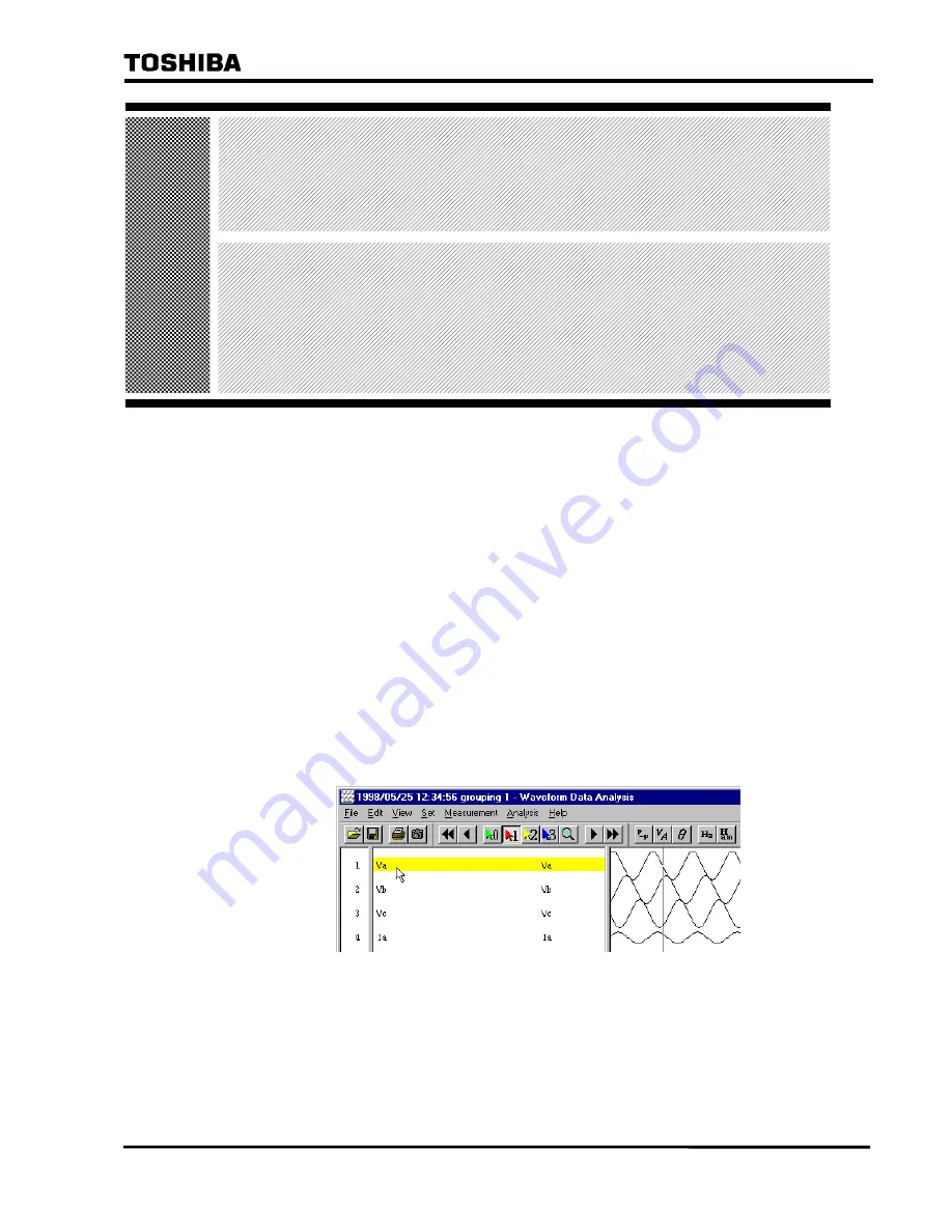
Click the element segment of the waveform from which you want to create a line or
zero-phase element (only 1).
1-24
Содержание RSM 100
Страница 29: ... 28 6 F 2 S 0 7 1 5 ...
Страница 70: ... 69 6 F 2 S 0 7 1 5 Appendix A Menu Tree ...
Страница 72: ... 71 6 F 2 S 0 7 1 5 Appendix B Waveform Data Analysis Instruction Manual ...
Страница 82: ... 81 6 F 2 S 0 7 1 5 The waveforms of the selected waveform data are displayed 1 5 ...
Страница 141: ... 140 6 F 2 S 0 7 1 5 Click OK button Vector Diagram box is displayed and the consecutive display starts 2 28 ...
Страница 149: ... 148 6 F 2 S 0 7 1 5 Memo 2 36 ...
Страница 158: ... 157 6 F 2 S 0 7 1 5 Memo 3 9 ...
Страница 159: ... 158 6 F 2 S 0 7 1 5 Waveform Data Analysis Instruction Manual FF02757 01 3 10 ...
Страница 160: ... 159 6 F 2 S 0 7 1 5 Appendix C Saving Method of RSM Setting Data ...
Страница 163: ... 162 6 F 2 S 0 7 1 5 ...
Страница 164: ... 163 6 F 2 S 0 7 1 5 Appendix D Q A ...
Страница 173: ......


