background image


RemotEye® ESS Instruction Manual 

– 201791-002


11


RemotEye

®

 ESS Web Application 

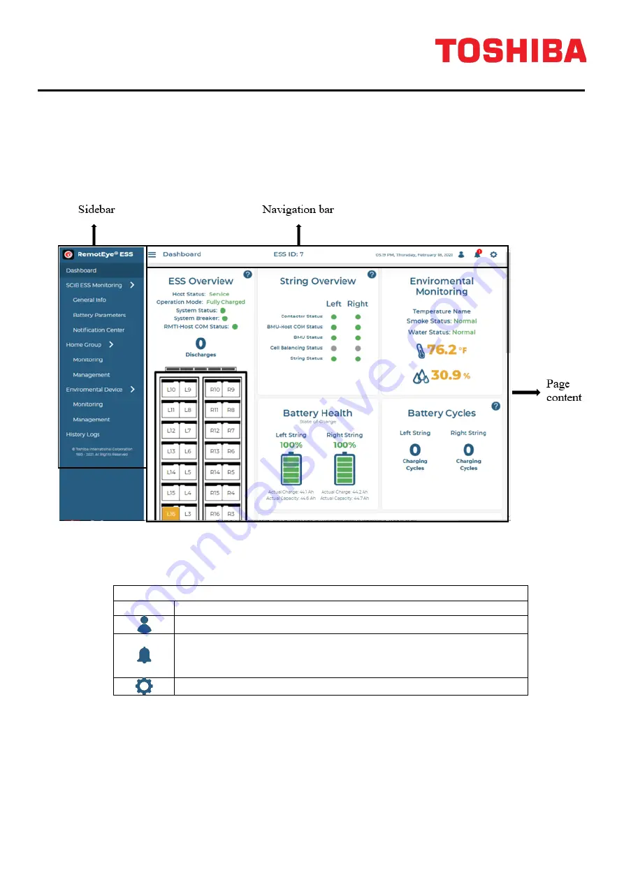
Dashboard 

After the first-time setup is completed, the first page that comes up when logged in or users visit the 
RemotEye® ESS web application is the "Dashboard" page. 


Navigation bar  

The navigation bar displays the basic information such as the current page, the ESS ID number, and 
RemotEye® ESS date & time. You can hover the cursor over the icon on the right of the navigation bar to 
quickly navigate to different pages 

Navigation bar icons 

Icon 

Description 


Click on this icon to login/logout. 


This icon indicates the number of active alarms in the 
system. Hover over this icon for alarm details. Click on this 
icon to navigate to the "Notification Center" page.  


Click on this icon to access the "Settings" page.  


Содержание RemotEye ESS

Страница 1: ...RemotEye ESS Energy Storage System Network Card Instruction Manual Document Number 201791 002 July 2021 ...

Страница 2: ......

Страница 3: ...on of this equipment must only be performed by qualified personnel The Instructions contained in this manual are not intended to cover all of the details or variations in equipment or to provide for every possible contingency to be met in connection with installation operation or maintenance Should further information be required or should particular problems arise which are not covered sufficient...

Страница 4: ...heir respective owners TOSHIBA shall not be liable for technical or editorial omissions or mistakes in this manual Nor shall it be liable for incidental or consequential damages resulting from the use of information contained in this manual This manual is copyrighted No part of this manual may be photocopied or reproduced in any form without the prior written consent of TOSHIBA INTERNATIONAL CORPO...

Страница 5: ...p 1 Ensure SCiB Cabinet and Network Connection 4 Step 2 Locate the RemotEye ESS IP Address 5 Step 3 First Time Setup 7 Step 4 Establish Communication between SCiB ESS and RemotEye ESS 8 RemotEye ESS Web Application 11 Dashboard 11 Navigation bar 11 Sidebar and Pages Description 12 Page Icons 12 History Logs 12 Settings 13 Configuring Settings with Web Browser 14 Initial Configuration 14 Modbus Set...

Страница 6: ...SCiB Dip Switch Number 25 Configuring EMD with Web Browser 26 Initial Configuration 26 Temperature Thresholds Settings 27 Humidity Thresholds Settings 28 Digital Inputs Settings 28 Firmware Upgrade 30 Tupgrade Procedure 30 Web Procedure 31 Automatic Upgrade 31 Manual Upgrade 31 Setup Port mini USB port 32 Frequently Asked Questions 34 Appendix A Technical Information 35 Modbus Register Table 35 LE...

Страница 7: ...rence when the equipment is operated in a commercial environment CE Notice This device complies with the EMC directive of the European Community and meets or exceeds the following technical standard EN55022 2010 Class B EN55024 2010 IEC 61000 4 2 2008 IEC 61000 4 3 2006 A1 2007 A2 2010 IEC 61000 4 4 2012 IEC 61000 4 5 2014 IEC 61000 4 6 2013 IEC 61000 4 8 2009 Safety Information All the service of...

Страница 8: ...ly via DHCP or BOOTP Key performance analytics Auto sensing 10 100Mbps fast Ethernet network port Simplified firmware upgrade process IPv4 and IPv6 dual stake RS 485 Support Supports Modbus TCP RTU SNMP and BACnet IP to connect industrial equipment Supports Environmental Monitoring Device EMD for ambient temperature and humidity monitoring RemotEye ESS System Application The following diagram show...

Страница 9: ...on RemotEye ESS includes a Network port Ethernet EMD port USB port Setup port RS 485 port and a Restart button as shown below No Item 1 Network port Connects to an Ethernet network LED indication LAN 10 100 link Activity 2 EMD port Connects to an environmental sensor EMD LED indication System power System status 3 USB port For future expansion capabilities 4 Setup port Connects to a workstation wi...

Страница 10: ...Eye ESS Checklist for Setup Know the MAC Address for your RemotEye ESS This is located on a sticker underneath the RemotEye ESS device Know the Dip Switch Number on the SCiB ESS Cabinet this RemotEye ESS will be connected to If you want the RemotEye ESS to use a static IP Address please know the IP Address Subnet Mask and Gateway Address you want your RemotEye ESS set to Step 1 Ensure SCiB Cabinet...

Страница 11: ...s all RemotEye units on your current network c Compare the MAC Addresses in the list then locate and note your RemotEye ESS s IP Address When connecting the RemotEye to an enabled DHCP network there is no need to adjust the IP settings If you wish to have a static IP address assigned to RemotEye or if you do not have a DHCP server continue on this step If NOT go to step 3 d Select the RemotEye ESS...

Страница 12: ...6 RemotEye ESS Instruction Manual 201791 002 List of RemotEye units on Network Selected RemotEye Edit Window ...

Страница 13: ...ndow Step 3 First Time Setup 1 Launch your web browser and enter your RemotEye ESS s IP Address into the search bar or select a RemotEye and click Browse within Tupgrade 2 Enter the default username TOSHIBA and password ADMIN to login and start the First Time Setup process ...

Страница 14: ... SCiB ESS and RemotEye ESS a After the first time setup log in again to become an administrator login with the credentials created in the first time setup b In the dashboard go to the top navigation bar and click the gear logo on the right to get to the settings Then click General and confirm the baud rate is set to 115200 and the SCiB Dip Switch Number is correctly identified under the About sect...

Страница 15: ...blished If there is no connection issue the dashboard should show the real time data of the SCiB ESS If there is a communication issue there will be a Connection Lost pop up If this is the case please check the communication cable between RemotEye ESS and the ESS cabinet and make sure they are securely connected ...

Страница 16: ...10 RemotEye ESS Instruction Manual 201791 002 ...

Страница 17: ...e basic information such as the current page the ESS ID number and RemotEye ESS date time You can hover the cursor over the icon on the right of the navigation bar to quickly navigate to different pages Navigation bar icons Icon Description Click on this icon to login logout This icon indicates the number of active alarms in the system Hover over this icon for alarm details Click on this icon to n...

Страница 18: ...lication Tooltip icons are hoverable to display definitions and user guidance Page icons Icon Description Pages This icon indicates a normal status It is used for informational alarms Dashboard Notification Center This icon indicates a warning status It is used for warning alarms This icon indicates a fault status It is used for fault alarms This icon is used for tooltip It is included in many dif...

Страница 19: ...MD General Extended Log By default it records in one hour intervals Thus it provides up to 28d 10h 40m 0s worth of data The polling rate can be customized for a longer period Max logs 4096 EMD Event Log Hold all events info warning and fault related to EMD Max logs 1024 Settings Changed History Log Logs the changes made to RemotEye ESS configurations and by whom Max logs 1024 Settings Click on the...

Страница 20: ...gs Ethernet Configurations Configuration Tool Backup Restore User Guide Security Modbus SNMP BACnet Settings section Related sections are grouped in one page on the Settings menu Tooltip Each setting section has a icon on the top right corner Hover the cursor over the tooltip icon to display more definitions and user guidance Configuring Settings with Web Browser Initial Configuration 1 Login to b...

Страница 21: ...lly Modbus Setup The following will help you set up your RemotEye ESS to communicate with another system via Modbus TCP or Modbus RTU Modbus TCP Setup 1 Login to become an administrator and go to the settings page by clicking the gear icon on the top navigation bar 2 Go to Modbus within the Protocol menu to set up Modbus settings 3 Toggle Modbus TCP IP Protocol to Enabled toggle should point to th...

Страница 22: ...sired baud rate 9600 19200 38400 57600 76800 115200 5 Enter the Modbus Address ID in the Address textbox field Default 1 6 Click Save to save the settings 7 Go to Serial Connection Configuration within the System menu and make sure that RS 485 Interface is enabled and that interface protocol is set to Modbus 8 Enable RS 485 Interface if not enabled 9 Verify that the Current RS 485 Interface Protoc...

Страница 23: ...BACnet IP BACnet IP Setup 1 Login to become an administrator and go to the settings page by clicking the gear icon on the top navigation bar 2 Go to BACnet within the Protocol menu to set up BACnet IP settings 3 Toggle BACnet IP Protocol to Enabled toggle should point to the right 4 Enter BACnet IP port number Default 47808 5 Click Save to save the settings 6 To see the objects list go to User Gui...

Страница 24: ...itoring System TMS is a monitoring service that allows Toshiba experts to monitor your SCiB ESS 24 7 If interested go to Toshiba Monitoring Service within the Settings menu and fill in the required information After submitting the form a TMS representative will call you to setup the service ...

Страница 25: ...toring System menu Upload the file that ends with the key extension in the Upload IoT Server Setup Key box Upload the file that ends with the pem extension in the Upload IoT Server Setup CA box Go to the Home tab and click the Connect button and wait for the connection status to change to connected Go to www toshibaups com cloud and login to view your device Note In order for the RemotEye ESS to e...

Страница 26: ... and Enable All The Enable All option will enable SNMPv1 v2c and SNMPv3 5 Enter an integer for Port Number By default Port Number is set to 161 6 For SNMPv1 v2c read and write community strings are required for communication By default the read community string is set to public string and the write community string is set to private string 7 For SNMPv3 a user account is required for communication ...

Страница 27: ...s with warning or fault events Fault will only send traps with fault events 8 Enter a reference note to identify the trap receiver This field is optional 9 Click the Save button to save the settings 10 Click the Test Trap button to send a trap test to confirm the settings HTTPS Setup HTTPS Protocol is supported in firmware version v2 0 0 2 and above 1 Login to become an Administrator and go to the...

Страница 28: ...lick on the Self Signed SSL tab of the HTTPS section and follow the steps to generate a new self signed certificate Custom SSL Click on the Custom SSL tab of the HTTPS section and follow the steps and the user guide page s example to create a custom SSL certificate ...

Страница 29: ... Settings This section allows enabling disabling network specific protocols To access this section login as an administrator and go to the Settings System page SSH This allows access to the RemotEye ESS console menu via SSH Network Upgrade This allows the user to perform a firmware upgrade via the network For more details on performing firmware upgrade go to Firmware Upgrade section UPnP Control U...

Страница 30: ...rator and go to the Settings General page Guest Mode This enables disables the Guest Mode button on the login screen If enabled it allows any user to login with read only access Default Enabled Login Screen This setting allows administrators to enable disable the login screen If disabled any user will be routed inside the RemotEye ESS with read only access Default Enabled ...

Страница 31: ... unit The temperature unit set will be reflected in all the temperature based parameters Once changes are made click the Save button to save It also allows the user to view the communication settings and status between RemotEye ESS and the SCiB ESS cabinet Baud Rate The RemotEye ESS and SCiB ESS maximum data transfer rate Default 115200 SCiB Dip Switch Number Dip Switch Number of the SCiB ESS Cabi...

Страница 32: ...sors that can be connected to its two digital inputs The EMD can be mounted up to 100 meters away from the RemotEye ESS 1 Mount the EMD device to the desired location and connect one end of the Cat 5 cable to the EMD communication port 2 Connect the other end of the Cat 5 cable to the RemotEye ESS EMD port 3 Login as an administrator and go to the Management page under Environmental Device located...

Страница 33: ... The RemotEye ESS allows users to configure temperature alarms to alert you whenever a temperature threshold has been reached Critical Low Enter the lowest environment temperature allowed Warning Low Enter the threshold when you want to be notified when temperature is getting close to critical low level This value must be higher than critical low setting Critical High Enter the highest environment...

Страница 34: ...tting close to critical high level This value has to be lower than critical high setting Humidity Calibration Offset This allows you to calibrate the EMD humidity sensor Digital Inputs Settings The EMD device has two digital inputs that allow users to connect two additional sensors that provide normal close open conditions such as door intrusion sensors If these sensors activate RemotEye ESS will ...

Страница 35: ...RemotEye ESS Instruction Manual 201791 002 29 ...

Страница 36: ...going to Settings System Network menu and enable Network Upgrade function 2 Open Tupgrade application and click on the Discover icon If no RemotEye ESS auto populates on the list click on the icon and enter the IP username and password If it still does not work please check with your network administrator to make sure that TFTP is allowed over the network 3 Select the checkbox right next to the Re...

Страница 37: ...r the Toshiba server s latest firmware This function requires internet access 3 If there is a new firmware click on the Upgrade button to proceed with the firmware update Manual Upgrade 1 Go to the Manual Upgrade tab of the Firmware Update section within the Settings General menu and upload or drag the file to the device 2 Click on the Upgrade button to proceed with the firmware update ...

Страница 38: ...with internet access is required Connect to PC 1 Connect the mini USB cable between RemotEye ESS Setup port and workstation PC Windows will automatically search for the device driver If successful get the COM number assigned in device manager application 2 Open terminal emulator software i e PuTTY 3 Set the connection type to serial and enter the COM port number assigned by Windows 4 Under Connect...

Страница 39: ...e ESS Instruction Manual 201791 002 33 5 Type in the Default Username if not previously changed TOSHIBA and Password ADMIN and press Enter 6 Once logged in successfully all the settings are available configure ...

Страница 40: ...ESS manual to locate the dip switch and how to read the value from it Or by going to the SCiB Communication Settings web page under Settings menu How do I perform a factory reset Forgot password In order to perform a factory reset you will need to have access to the physical RemotEye ESS The steps below will set all the settings to default Please note that this will reset IP address and user crede...

Страница 41: ...fault Both contactors are closed Ready If bit is one system has no fault One or more contactors is open Abnormal If bit is one system is in fault or short start up period Both contactors are open Cabinet fault status 40011 Real Time N A Reserved Host Host CAN COM fault 1 true 0 false Tray open 1 true 0 false Fuse open 1 true 0 false Breaker open 1 true 0 false Left string fault status 40012 Real T...

Страница 42: ...tery Number of Cells b0 b8 Battery Max Charging Current b9 b15 40802 Config N A x1 Amps 32 432 Fully charged string voltage 40015 Config x0 1 Volts Fully charged voltage indicated by 0 1V LSB 570V Cutoff string voltage 40016 Config x0 1 Volts Cutoff voltage indicated by 0 1V LSB 455V Over charge current warning 40017 Config x0 01 Amps Over charge current value indicated by 0 01A LSB 40A Over disch...

Страница 43: ...it will only display cabinet ID If system has warning or fault it will display repeatedly in the sequence of cabinet ID warning cabinet fault left string fault and right string fault Each of them will be displayed for 5 sec with 5 sec interval of LED blank after During the 5 sec display the cabinet ID 1 digit will be on always the warning or fault status 5 digits will display from the highest digi...

Страница 44: ...ge 40 C to 125 C Right string average temp value of all cells in indicated by 1 C LSB Usage range 40 C to 125 C Left string min cell voltage 40043 Real Time x0 001 Volts Left string min voltage value of all cells indicated by 1mV LSB Left string max cell voltage 40044 Real Time x0 001 Volts Left string max voltage value of all cells indicated by 1mV LSB Left string min max cell voltage module No 4...

Страница 45: ... Cell 10 Module 1 Cell Voltage Cell 21 22 40096 Real Time x0 001 Volts Module 1 Cell Voltage Cell 11 Module 1 Cell Voltage Cell 23 24 40097 Real Time x0 001 Volts Module 1 Cell Voltage Cell 12 Module 1 Cell Temperature 1 40098 Real Time Temperature Unit Module 1 Cell Temperature 1 Module 1 Cell Temperature 2 40099 Real Time Temperature Unit Module 1 Cell Temperature 2 Module 1 Cell Temperature 3 4...

Страница 46: ...perature 2 Module 2 Cell Temperature 3 40118 Real Time Temperature Unit Module 2 Cell Temperature 3 Module 2 Cell Temperature 4 40119 Real Time Temperature Unit Module 2 Cell Temperature 4 Module 2 Cell Temperature 5 40120 Real Time Temperature Unit Module 2 Cell Temperature 5 Module 2 Cell Temperature 6 40121 Real Time Temperature Unit Module 2 Cell Temperature 6 Module 3 Cell Voltage Cell 1 2 40...

Страница 47: ...6 Module 4 Cell Voltage Cell 1 2 40140 Real Time x0 001 Volts Module 4 Cell Voltage Cell 1 Module 4 Cell Voltage Cell 3 4 40141 Real Time x0 001 Volts Module 4 Cell Voltage Cell 2 Module 4 Cell Voltage Cell 5 6 40142 Real Time x0 001 Volts Module 4 Cell Voltage Cell 3 Module 4 Cell Voltage Cell 7 8 40143 Real Time x0 001 Volts Module 4 Cell Voltage Cell 4 Module 4 Cell Voltage Cell 9 10 40144 Real...

Страница 48: ...dule 5 Cell Voltage Cell 9 10 40162 Real Time x0 001 Volts Module 5 Cell Voltage Cell 5 Module 5 Cell Voltage Cell 11 12 40163 Real Time x0 001 Volts Module 5 Cell Voltage Cell 6 Module 5 Cell Voltage Cell 13 14 40164 Real Time x0 001 Volts Module 5 Cell Voltage Cell 7 Module 5 Cell Voltage Cell 15 16 40165 Real Time x0 001 Volts Module 5 Cell Voltage Cell 8 Module 5 Cell Voltage Cell 17 18 40166 ...

Страница 49: ...ll 8 Module 6 Cell Voltage Cell 17 18 40184 Real Time x0 001 Volts Module 6 Cell Voltage Cell 9 Module 6 Cell Voltage Cell 19 20 40185 Real Time x0 001 Volts Module 6 Cell Voltage Cell 10 Module 6 Cell Voltage Cell 21 22 40186 Real Time x0 001 Volts Module 6 Cell Voltage Cell 11 Module 6 Cell Voltage Cell 23 24 40187 Real Time x0 001 Volts Module 6 Cell Voltage Cell 12 Module 6 Cell Temperature 1 ...

Страница 50: ...tage Cell 12 Module 7 Cell Temperature 1 40206 Real Time Temperature Unit Module 7 Cell Temperature 1 Module 7 Cell Temperature 2 40207 Real Time Temperature Unit Module 7 Cell Temperature 2 Module 7 Cell Temperature 3 40208 Real Time Temperature Unit Module 7 Cell Temperature 3 Module 7 Cell Temperature 4 40209 Real Time Temperature Unit Module 7 Cell Temperature 4 Module 7 Cell Temperature 5 402...

Страница 51: ...ure 4 Module 8 Cell Temperature 5 40228 Real Time Temperature Unit Module 8 Cell Temperature 5 Module 8 Cell Temperature 6 40229 Real Time Temperature Unit Module 8 Cell Temperature 6 Module 9 Cell Voltage Cell 1 2 40230 Real Time x0 001 Volts Module 9 Cell Voltage Cell 1 Module 9 Cell Voltage Cell 3 4 40231 Real Time x0 001 Volts Module 9 Cell Voltage Cell 2 Module 9 Cell Voltage Cell 5 6 40232 R...

Страница 52: ...ll Voltage Cell 5 6 40250 Real Time x0 001 Volts Module 10 Cell Voltage Cell 3 Module 10 Cell Voltage Cell 7 8 40251 Real Time x0 001 Volts Module 10 Cell Voltage Cell 4 Module 10 Cell Voltage Cell 9 10 40252 Real Time x0 001 Volts Module 10 Cell Voltage Cell 5 Module 10 Cell Voltage Cell 11 12 40253 Real Time x0 001 Volts Module 10 Cell Voltage Cell 6 Module 10 Cell Voltage Cell 13 14 40254 Real ...

Страница 53: ...ule 11 Cell Voltage Cell 13 14 40272 Real Time x0 001 Volts Module 11 Cell Voltage Cell 7 Module 11 Cell Voltage Cell 15 16 40273 Real Time x0 001 Volts Module 11 Cell Voltage Cell 8 Module 11 Cell Voltage Cell 17 18 40274 Real Time x0 001 Volts Module 11 Cell Voltage Cell 9 Module 11 Cell Voltage Cell 19 20 40275 Real Time x0 001 Volts Module 11 Cell Voltage Cell 10 Module 11 Cell Voltage Cell 21...

Страница 54: ...l 10 Module 12 Cell Voltage Cell 21 22 40294 Real Time x0 001 Volts Module 12 Cell Voltage Cell 11 Module 12 Cell Voltage Cell 23 24 40295 Real Time x0 001 Volts Module 12 Cell Voltage Cell 12 Module 12 Cell Temperature 1 40296 Real Time Temperature Unit Module 12 Cell Temperature 1 Module 12 Cell Temperature 2 40297 Real Time Temperature Unit Module 12 Cell Temperature 2 Module 12 Cell Temperatur...

Страница 55: ...ture 2 Module 13 Cell Temperature 3 40316 Real Time Temperature Unit Module 13 Cell Temperature 3 Module 13 Cell Temperature 4 40317 Real Time Temperature Unit Module 13 Cell Temperature 4 Module 13 Cell Temperature 5 40318 Real Time Temperature Unit Module 13 Cell Temperature 5 Module 13 Cell Temperature 6 40319 Real Time Temperature Unit Module 13 Cell Temperature 6 Module 14 Cell Voltage Cell 1...

Страница 56: ...dule 15 Cell Voltage Cell 1 2 40338 Real Time x0 001 Volts Module 15 Cell Voltage Cell 1 Module 15 Cell Voltage Cell 3 4 40339 Real Time x0 001 Volts Module 15 Cell Voltage Cell 2 Module 15 Cell Voltage Cell 5 6 40340 Real Time x0 001 Volts Module 15 Cell Voltage Cell 3 Module 15 Cell Voltage Cell 7 8 40341 Real Time x0 001 Volts Module 15 Cell Voltage Cell 4 Module 15 Cell Voltage Cell 9 10 40342...

Страница 57: ... 16 Cell Voltage Cell 9 10 40360 Real Time x0 001 Volts Module 16 Cell Voltage Cell 5 Module 16 Cell Voltage Cell 11 12 40361 Real Time x0 001 Volts Module 16 Cell Voltage Cell 6 Module 16 Cell Voltage Cell 13 14 40362 Real Time x0 001 Volts Module 16 Cell Voltage Cell 7 Module 16 Cell Voltage Cell 15 16 40363 Real Time x0 001 Volts Module 16 Cell Voltage Cell 8 Module 16 Cell Voltage Cell 17 18 4...

Страница 58: ... Module 17 Cell Voltage Cell 17 18 40382 Real Time x0 001 Volts Module 17 Cell Voltage Cell 9 Module 17 Cell Voltage Cell 19 20 40383 Real Time x0 001 Volts Module 17 Cell Voltage Cell 10 Module 17 Cell Voltage Cell 21 22 40384 Real Time x0 001 Volts Module 17 Cell Voltage Cell 11 Module 17 Cell Voltage Cell 23 24 40385 Real Time x0 001 Volts Module 17 Cell Voltage Cell 12 Module 17 Cell Temperatu...

Страница 59: ... 18 Cell Temperature 1 40404 Real Time Temperature Unit Module 18 Cell Temperature 1 Module 18 Cell Temperature 2 40405 Real Time Temperature Unit Module 18 Cell Temperature 2 Module 18 Cell Temperature 3 40406 Real Time Temperature Unit Module 18 Cell Temperature 3 Module 18 Cell Temperature 4 40407 Real Time Temperature Unit Module 18 Cell Temperature 4 Module 18 Cell Temperature 5 40408 Real Ti...

Страница 60: ...ure 4 Module 1 Cell Temperature 5 40426 Real Time Temperature Unit Module 1 Cell Temperature 5 Module 1 Cell Temperature 6 40427 Real Time Temperature Unit Module 1 Cell Temperature 6 Module 2 Cell Voltage Cell 1 2 40428 Real Time x0 001 Volts Module 2 Cell Voltage Cell 1 Module 2 Cell Voltage Cell 3 4 40429 Real Time x0 001 Volts Module 2 Cell Voltage Cell 2 Module 2 Cell Voltage Cell 5 6 40430 R...

Страница 61: ...odule 3 Cell Voltage Cell 5 6 40448 Real Time x0 001 Volts Module 3 Cell Voltage Cell 3 Module 3 Cell Voltage Cell 7 8 40449 Real Time x0 001 Volts Module 3 Cell Voltage Cell 4 Module 3 Cell Voltage Cell 9 10 40450 Real Time x0 001 Volts Module 3 Cell Voltage Cell 5 Module 3 Cell Voltage Cell 11 12 40451 Real Time x0 001 Volts Module 3 Cell Voltage Cell 6 Module 3 Cell Voltage Cell 13 14 40452 Rea...

Страница 62: ... Module 4 Cell Voltage Cell 13 14 40470 Real Time x0 001 Volts Module 4 Cell Voltage Cell 7 Module 4 Cell Voltage Cell 15 16 40471 Real Time x0 001 Volts Module 4 Cell Voltage Cell 8 Module 4 Cell Voltage Cell 17 18 40472 Real Time x0 001 Volts Module 4 Cell Voltage Cell 9 Module 4 Cell Voltage Cell 19 20 40473 Real Time x0 001 Volts Module 4 Cell Voltage Cell 10 Module 4 Cell Voltage Cell 21 22 4...

Страница 63: ... Cell 10 Module 5 Cell Voltage Cell 21 22 40492 Real Time x0 001 Volts Module 5 Cell Voltage Cell 11 Module 5 Cell Voltage Cell 23 24 40493 Real Time x0 001 Volts Module 5 Cell Voltage Cell 12 Module 5 Cell Temperature 1 40494 Real Time Temperature Unit Module 5 Cell Temperature 1 Module 5 Cell Temperature 2 40495 Real Time Temperature Unit Module 5 Cell Temperature 2 Module 5 Cell Temperature 3 4...

Страница 64: ...perature 2 Module 6 Cell Temperature 3 40516 Real Time Temperature Unit Module 6 Cell Temperature 3 Module 6 Cell Temperature 4 40517 Real Time Temperature Unit Module 6 Cell Temperature 4 Module 6 Cell Temperature 5 40518 Real Time Temperature Unit Module 6 Cell Temperature 5 Module 6 Cell Temperature 6 40519 Real Time Temperature Unit Module 6 Cell Temperature 6 Module 7 Cell Voltage Cell 1 2 40...

Страница 65: ...6 Module 8 Cell Voltage Cell 1 2 40538 Real Time x0 001 Volts Module 8 Cell Voltage Cell 1 Module 8 Cell Voltage Cell 3 4 40539 Real Time x0 001 Volts Module 8 Cell Voltage Cell 2 Module 8 Cell Voltage Cell 5 6 40540 Real Time x0 001 Volts Module 8 Cell Voltage Cell 3 Module 8 Cell Voltage Cell 7 8 40541 Real Time x0 001 Volts Module 8 Cell Voltage Cell 4 Module 8 Cell Voltage Cell 9 10 40542 Real...

Страница 66: ...dule 9 Cell Voltage Cell 9 10 40560 Real Time x0 001 Volts Module 9 Cell Voltage Cell 5 Module 9 Cell Voltage Cell 11 12 40561 Real Time x0 001 Volts Module 9 Cell Voltage Cell 6 Module 9 Cell Voltage Cell 13 14 40562 Real Time x0 001 Volts Module 9 Cell Voltage Cell 7 Module 9 Cell Voltage Cell 15 16 40563 Real Time x0 001 Volts Module 9 Cell Voltage Cell 8 Module 9 Cell Voltage Cell 17 18 40564 ...

Страница 67: ...Module 10 Cell Voltage Cell 17 18 40582 Real Time x0 001 Volts Module 10 Cell Voltage Cell 9 Module 10 Cell Voltage Cell 19 20 40583 Real Time x0 001 Volts Module 10 Cell Voltage Cell 10 Module 10 Cell Voltage Cell 21 22 40584 Real Time x0 001 Volts Module 10 Cell Voltage Cell 11 Module 10 Cell Voltage Cell 23 24 40585 Real Time x0 001 Volts Module 10 Cell Voltage Cell 12 Module 10 Cell Temperatur...

Страница 68: ... Cell 12 Module 11 Cell Temperature 1 40604 Real Time Temperature Unit Module 11 Cell Temperature 1 Module 11 Cell Temperature 2 40605 Real Time Temperature Unit Module 11 Cell Temperature 2 Module 11 Cell Temperature 3 40606 Real Time Temperature Unit Module 11 Cell Temperature 3 Module 11 Cell Temperature 4 40607 Real Time Temperature Unit Module 11 Cell Temperature 4 Module 11 Cell Temperature ...

Страница 69: ...4 Module 12 Cell Temperature 5 40626 Real Time Temperature Unit Module 12 Cell Temperature 5 Module 12 Cell Temperature 6 40627 Real Time Temperature Unit Module 12 Cell Temperature 6 Module 13 Cell Voltage Cell 1 2 40628 Real Time x0 001 Volts Module 13 Cell Voltage Cell 1 Module 13 Cell Voltage Cell 3 4 40629 Real Time x0 001 Volts Module 13 Cell Voltage Cell 2 Module 13 Cell Voltage Cell 5 6 40...

Страница 70: ...e 14 Cell Voltage Cell 5 6 40648 Real Time x0 001 Volts Module 14 Cell Voltage Cell 3 Module 14 Cell Voltage Cell 7 8 40649 Real Time x0 001 Volts Module 14 Cell Voltage Cell 4 Module 14 Cell Voltage Cell 9 10 40650 Real Time x0 001 Volts Module 14 Cell Voltage Cell 5 Module 14 Cell Voltage Cell 11 12 40651 Real Time x0 001 Volts Module 14 Cell Voltage Cell 6 Module 14 Cell Voltage Cell 13 14 4065...

Страница 71: ...ule 15 Cell Voltage Cell 13 14 40670 Real Time x0 001 Volts Module 15 Cell Voltage Cell 7 Module 15 Cell Voltage Cell 15 16 40671 Real Time x0 001 Volts Module 15 Cell Voltage Cell 8 Module 15 Cell Voltage Cell 17 18 40672 Real Time x0 001 Volts Module 15 Cell Voltage Cell 9 Module 15 Cell Voltage Cell 19 20 40673 Real Time x0 001 Volts Module 15 Cell Voltage Cell 10 Module 15 Cell Voltage Cell 21...

Страница 72: ...l 10 Module 16 Cell Voltage Cell 21 22 40692 Real Time x0 001 Volts Module 16 Cell Voltage Cell 11 Module 16 Cell Voltage Cell 23 24 40693 Real Time x0 001 Volts Module 16 Cell Voltage Cell 12 Module 16 Cell Temperature 1 40694 Real Time Temperature Unit Module 16 Cell Temperature 1 Module 16 Cell Temperature 2 40695 Real Time Temperature Unit Module 16 Cell Temperature 2 Module 16 Cell Temperatur...

Страница 73: ...ture 2 Module 17 Cell Temperature 3 40714 Real Time Temperature Unit Module 17 Cell Temperature 3 Module 17 Cell Temperature 4 40715 Real Time Temperature Unit Module 17 Cell Temperature 4 Module 17 Cell Temperature 5 40716 Real Time Temperature Unit Module 17 Cell Temperature 5 Module 17 Cell Temperature 6 40717 Real Time Temperature Unit Module 17 Cell Temperature 6 Module 18 Cell Voltage Cell 1...

Страница 74: ...mperature Unit Module 18 Cell Temperature 5 Module 18 Cell Temperature 6 40735 Real Time Temperature Unit Module 18 Cell Temperature 6 CMU Registers Left String CMU STATUS BYTE 1 40736 Real Time Left String CMU STATUS BYTE 1 Left String CMU STATUS BYTE 2 40737 Real Time Left String CMU STATUS BYTE 2 Left String CMU STATUS BYTE 3 40738 Real Time Left String CMU STATUS BYTE 3 Left String CMU STATUS ...

Страница 75: ...14 Voltage Module 15 Voltage 41014 Real Time x0 001 Volts Module 15 Voltage Module 16 Voltage 41015 Real Time x0 001 Volts Module 16 Voltage Module 17 Voltage 41016 Real Time x0 001 Volts Module 17 Voltage Module 18 Voltage 41017 Real Time x0 001 Volts Module 18 Voltage Module 1 Average Temperature 41018 Real Time Temperature Unit Module 1 Average Temperature Module 2 Average Temperature 41019 Rea...

Страница 76: ...3 Real Time Temperature Unit Module 16 Average Temperature Module 17 Average Temperature 41034 Real Time Temperature Unit Module 17 Average Temperature Module 18 Average Temperature 41035 Real Time Temperature Unit Module 18 Average Temperature Right String BMU2 Module Level View Registers Module 1 Voltage 41036 Real Time x0 001 Volts Module 1 Voltage Module 2 Voltage 41037 Real Time x0 001 Volts ...

Страница 77: ...perature Module 5 Average Temperature 41058 Real Time Temperature Unit Module 5 Average Temperature Module 6 Average Temperature 41059 Real Time Temperature Unit Module 6 Average Temperature Module 7 Average Temperature 41060 Real Time Temperature Unit Module 7 Average Temperature Module 8 Average Temperature 41061 Real Time Temperature Unit Module 8 Average Temperature Module 9 Average Temperatur...

Страница 78: ...1 active 0 inactive Humidity is at Low Critical Point 1 active 0 inactive Alarm 2 1 active 0 inactive Alarm 1 1 active 0 inactive EMD Enabled 1 enabled 0 disabled RemotEye ESS Info Registers Software Version Major and Minor 41200 Config N A Major Number Minor Number Software Version Maintenance 41201 Config N A Maintenance Number Software Version Build 41202 Config N A Build Number ESS Data Link 4...

Страница 79: ...al Time Delta Environmental Nominal Humidity Estimated Left String Charging Cycles 41257 Real Time N A Estimated Left String Charging Cycles Estimated Right String Charging Cycles 41258 Real Time N A Estimated Right String Charging Cycles Left String Last Charging Cycle Time 41259 Real Time N A MM DD YY Right String Last Charging Cycle Time 41260 Real Time N A MM DD YY Left String SOH 41261 Real T...

Страница 80: ...EDs as listed in the following tables No Port Green LED Yellow LED Function 1 Network ON Flashing Ethernet 100 Traffic 2 OFF Flashing Ethernet 10 Traffic 3 ON OFF 100 Base TX Ready 4 OFF ON 10 Base T Ready 5 OFF OFF Ethernet Disconnection 6 Status EMD ON OFF Power On Normal Status 7 ON Flashing RS232 Port Activity 8 OFF OFF Hardware Error ...

Страница 81: ...ential that the reflections in the transmission line be kept as small as possible This can only be done by proper cable termination Reflections happen very quickly during and just after signal transitions On a long line the reflections are more likely to continue long enough to cause the receiver to misread logic levels On short lines the reflections occur much sooner and have no effect on the rec...

Страница 82: ...76 RemotEye ESS Instruction Manual 201791 002 ...

Страница 83: ...RemotEye ESS Instruction Manual 201791 002 77 This Page Left Intentionally Blank ...

Страница 84: ......

Страница 85: ......

Страница 86: ...NFRASTRUCTURE SYSTEMS GROUP POWER ELECTRONICS DIVISION 13131 West Little York Rd Houston TX 77041 Tel 855 803 7087 Fax 713 896 5212 US 800 231 1412 Canada 800 872 2192 Mexico 01 800 527 1204 www toshibaups com ...

Отзывы: