Toshiba RBM-Y1801F4PE Скачать руководство пользователя страница 6

EN-10

EN-9

5

4

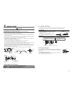
INSTALLATION OF FLOW SELECTOR 

UNIT

 WARNING

Install the unit securely in the place to suf

fi

 ciently withstand the weight of the unit.

If the foundation is not sturdy enough, the unit may fall and cause personal injury.

Perform a speci

fi

 ed installation work to guard against earthquake.

Improper installation may cause the unit to fall.

REQUIREMENT

Strictly comply with the following rules to prevent damage of the Flow Selector unit and human injury.
•  Do not put a heavy article on the Flow Selector unit or let a person get on it. (Even units are packaged)
•  Carry in the Flow Selector unit as it is packaged if possible. If carrying in the Flow Selector unit unpacked by 

necessity, use buffering cloth or other material to not damage the Flow Selector unit.

•  To move the Flow Selector unit, hold the hooking brackets (4 positions) only.
  Do not apply force to the other parts (refrigerant pipe, drain pan, foamed parts, resin parts or other parts).
•  Carry the package by two or more persons, and do not bundle it with plastic band at positions other than 

speci

fi

 ed.


„

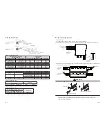
Installation of hanging bolt

•  Consider the piping / wiring before the unit is hung to determine the location of the Flow Selector unit installation 

and orientation.

•  After the location of the Flow Selector unit installation has been determined, install hanging bolts.
•  For the dimensions of the hanging bolt pitches, refer to the external view.
•  When a ceiling already exists, lay the drain pipe, refrigerant pipe, control wires, and remote controller wires to 

their connection locations before hanging the Flow Selector unit.

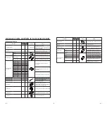
Procure hanging bolts washer and nuts for installing the Flow Selector unit (these are not supplied).

Hanging bolt

M10 or W3/8

4 pieces

Nut

M10 or W3/8

12 pieces


„

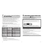
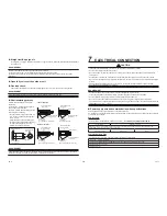
Installation under high-humidity atmosphere

In some cases including the rainy season, especially inside of the ceiling may become high-humidity atmosphere
(dew-point temperature: 23 °C or higher).

1. Installation to inside of the ceiling with tiles on the roof
2. Installation to inside of the ceiling with slated roof
3. Installation to a place where inside of the ceiling is used for pathway to intake the fresh air
4. Installation to a kitchen

•  In the above cases, additionally attach the heat insulator to all positions of the air conditioner, which come to 

contact with the high-humidity atmosphere. In this case, arrange the side plate (Check port) so that it is easily 
removed.

[Reference]


Condensation test conditions
Indoor side:  27 °C dry bulb temperature
   

24 °C wet bulb temperature

Air volume: Low air volume, operation time 4 hours


„

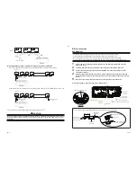
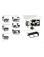
Installation and service space

Reserve suf

fi

 cient space required for installation or service work.

•  Make space for installation and service. (Make space to the electrical parts box cover side for service.)
•  When installing the unit inside the ceiling, be sure to create a check port.
  The check port is required when the unit is installed and serviced.
•  Keep a clearance of 150mm or more between the top panel of the unit and the ceiling.
•  The length of a connection pipe to the indoor unit should be 50m or less.

<Installation space>

(Unit : mm)


70


150 or more

100 or more

550 or more

550 or more

Bolt size : M10 or Ø3/8 (

fi

 eld supply)

Service hole 

…

 450

Service hole 

…

 450

Check port

50 or more

50 or more

Enough space to connect 
the site pipe

Control Box

600 or more

450 or more

Содержание RBM-Y1801F4PE

Страница 1: ...INSTALLATION MANUAL 1 English RBM Y1801F4PE RBM Y1801F6PE Installation Manual Multi Port Flow Selector Unit ...

Страница 2: ...hoose one according to the capacity of the units ADOPTION OF NEW REFRIGERANT This Super Heat Recovery Multi Air Conditioner is a new type which adopts a new refrigerant HFC R410A instead of the conventional refrigerant R22 in order to prevent destruction of the ozone layer Be sure to use an indoor or outdoor unit in combination with the new refrigerant CONTENTS Accessory parts and Parts to be proc...

Страница 3: ...Ø22 2 Ø15 9 1 1 Ø22 2 Ø12 7 1 1 Ø22 2 Ø9 5 1 1 Binding band L300 2 2 For fixing heat insulation of flexible hose Binding band L200 16 24 For fixing heat insulating pipes Binding band L100 5 7 For fixing clamp filters Clamp filter 5 7 For reducing electrical noise of communication wires and float switch wire of drain pump locally procured Cable clamp 6 8 For fixing indoor unit communication cables ...

Страница 4: ...t to enter any gaseous matter other than the specified refrigerant into the refrigeration cycle If air or any other gas is mixed in the refrigerant the gas pressure in the refrigeration cycle becomes abnormally high and it as a result causes pipe burst and injuries on persons Do not modify this unit by removing any of the safety guards or by by passing any of the safety interlock switches Exposure...

Страница 5: ...gerant piping Piping material used for the conventional refrigerant cannot be used Use copper pipe with 0 8mm or more thickness for Ø6 4 Ø9 5 Ø12 7mm Use copper pipe with 1 0mm or more thickness for Ø15 9mm Ø19 1mm Ø22 2mm or more Use clean and new pipes for the refrigerant pipes and perform piping work so that water or dust does not contaminate the refrigerant 3 SELECTION OF INSTALLATION PLACE CA...

Страница 6: ...ow Selector unit Procure hanging bolts washer and nuts for installing the Flow Selector unit these are not supplied Hanging bolt M10 or W3 8 4 pieces Nut M10 or W3 8 12 pieces Installation under high humidity atmosphere In some cases including the rainy season especially inside of the ceiling may become high humidity atmosphere dew point temperature 23 C or higher 1 Installation to inside of the c...

Страница 7: ...al level of installed ceiling correctly in order to prevent vibration of ceiling board Attach the nuts and the M10 flat washers to the hanging bolt Put washers at up and down of the hanging bracket of the Flow Selector unit to hang down the Flow Selector unit Check that four sides are horizontal with a level gauge Horizontal degree Within 5 mm Hanging bolt W3 8 or M10 70 mm or less M10 flat washer...

Страница 8: ...o the unit with proper heat insulation Improper heat insulation will cause condensation to form The drain pipe must be sloping downward at an angle of 1 100 or more and do not run the pipe up and down arched shape or allow it to form traps Doing so may cause abnormal sounds Restrict the length of the traversing drain pipe to 20 meters or less For a long pipe provide support brackets at intervals o...

Страница 9: ...es not leak from the connect the pipes Check port Plastic container to pour water 6 REFRIGERANT PIPING WARNING If refrigerant gas has leaked during the installation work ventilate the room immediately If the leaked refrigerant gas comes in contact with fire noxious gas may be generated After the installation work confirm that refrigerant gas does not leak If refrigerant gas leaks into the room and...

Страница 10: ... connection per one port Outdoor unit side pipe size 1 Total capacity codes of indoor units at the downstream side Outdoor unit side Upstream Equivalent to capacity Equivalent to HP Suction gas pipe Discharge gas pipe Liquid pipe Below 18 0 Below 6 4 Ø15 9 Ø12 7 Ø9 5 18 0 to below 34 0 6 4 to below 12 2 Ø22 2 Ø19 1 Ø12 7 34 0 to below 45 5 12 2 to below 16 2 Ø28 6 Ø22 2 Ø15 9 45 5 to below 56 5 16...

Страница 11: ...re of the pipe The pipe exposed to the outside causes water leak 7 ELECTRICAL CONNECTION CAUTION If incorrect incomplete wiring is carried out it will cause an electrical fire or smoke Use the cord clamps attached to the product Do not damage or scratch the conductive core and inner insulator of power and communication wires when peeling them Use the power cord and communication wire of specified ...

Страница 12: ...pply terminal block Cable clamp Accessory Clamp all cables Terminal on PCB for Communication wiring Communication wire Clamp the communication wire Detail a For each communication wire attach the Clamp filter accessory as the picture below Clamp filter Accessory Hook 2 nails Communication wire locally procured 1 turn Attach round shaped terminal locally procured Clamp filter Accessory Binding band...

Страница 13: ...ng wires to the terminal 2 mm or less Communication wire Communication wiring A B A B Terminal block for remote controller wiring of indoor unit Communication wires locally procured FS unit terminal on PCB It s possible to come out the communication wires on the right side Cable clamp Accessory Clamp all cables Communication wire ...

Страница 14: ...r power switch Header outdoor unit Follower outdoor unit Earth terminal Earth terminal Control wiring between outdoor units Control wiring between indoor and outdoor units Control wiring between indoor units Indoor unit Indoor unit Indoor unit Indoor unit Earth Earth Earth Earth Pull box Pull box Pull box Remote controller Remote controller Remote controller Earth Earth Indoor unit FS unit power s...

Страница 15: ...r setup of address When connecting the indoor units to a branch of FS unit it is possible to connect with multiple groups and connect individually Indoor unit Piping FS unit Remote controller Group control How to set up CODE No 0E It is necessary to set up in case of the group control 2 4 1 3 5 1 Push and hold the and buttons at the same time for more than 4 seconds is displayed in the UNIT No win...

Страница 16: ...Group control Group control Indoor unit In case of connecting Drain pump locally procured It s available to connect the operation off signal input cable of float switch At that time the cable is taken from the hole on the control box bottom side and connect to CN34 on PC board of unit No 1 showing 1 on the label Be sure to connect the energized indoor unit to unit No 1 of FS unit Attach Rubber bus...

Страница 17: ...1118430099 TOSHIBA CARRIER THAILAND CO LTD 144 9 MOO 5 BANGKADI INDUSTRIAL PARK TIVANON ROAD TAMBOL BANGKADI AMPHUR MUANG PATHUMTHANI 12000 THAILAND ...

Отзывы: