


EN-30
EN-29
15
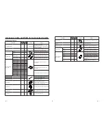
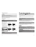
<In case of connecting two group operations of
indoor units>
Indoor unit
FS unit
Remote
controller
[ 0E ] :
1
1
1
1
[ FE ] :
1
1
1
1
[ FD ] :
0
0
0
0
Piping
Group control
Group control
<In case of connecting one group operation of
indoor units and two indoor units>
Indoor unit
FS unit
Remote
controller
[ 0E ] :
1
1
0
0
[ FE ] :
1
1
1
1
[ FD ] :
0
0
0
0
Piping
Group control
<In case of connecting four indoor units>
Indoor unit
FS unit
Remote controller
[ 0E ] :
0
0
0
0
[ FE ] :
1
1
1
1
[ FD ] :
0
0
0
0
Piping
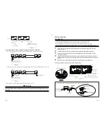
<Incorrect connection examples>
Incorrect
Incorrect
Incorrect
Indoor
unit
FS unit
FS unit
FS unit
Multi port type FS unit
Remote controller
Remote controller
Remote controller
Piping
Group control
Single port type FS unit
Piping
Piping
Indoor
unit
Group control
Group control
Indoor
unit
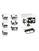
In case of connecting Drain pump (locally procured)
It's available to connect the operation-off signal input cable of
fl
oat switch.
At that time, the cable is taken from the hole on the control-box bottom side and connect to CN34 on PC board
of unit No.1 (showing "1" on the label).
Be sure to connect the energized indoor unit to unit No.1 of FS unit.
Attach Rubber-bushing (accessory) to the hole to prevent the cable is damaged by edge of hole. The length of
a
fl
oat switch cable should be 5 m or less.
90
20
B
A
Attach Clamp-
fi
lter
(accessory)
Connect
to CN34
To turn at once
in the
fi
lter
Binding band
(accessory)
Control box
Float switch cable
(locally procured)
Attach Rubber-bushing
(accessory)
Cut away
Communication wire
In case of connecting
fl
oat switch, concatenate between each CN34 of all P.C.board with wires (locally
procured).
Concatenate between
each CN34 with wires
(locally procured)


