– 3
7
–
FILE NO. SVM-13047
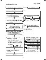
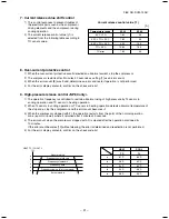
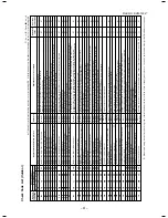
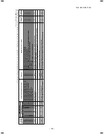
Frequency normal down
Frequency slow down
Frequency hold
Frequency slow up
(Up to command)
As command is
Abnormal stop
TD [˚C]
(117) 111
(107) 109
(105) 106
(102) 103
(93) 96
SP56 in the
parentheses
1. PMV (Pulse Motor Valve) control
1) PMV is controlled between (SP56: 20 to 500, SP80: 30 to 500) pulsed during operation.
2) In cooling operation, PMV is usually controlled with the temperature difference between TS sensor and
TC sensor aiming (SP56: 2 to 5K, SP80: 1 to 4K) as the target value.
3) In heating operation, PMV is usually controlled with the temperature difference between TS sensor and
TE sensor aiming (SP56: –2 to 4K, SP80: 2 to 4K) as the target value.
4) When the cycle excessively heated in both cooling and heating operation, PMV is controlled by TD sensor.
The target value is 101°C for both cooling and heating operations in SP56, and 91°C for cooling
operation and 96°C for heating operation respectively in SP80.
REQUIREMENT
A sensor trouble may cause a liquid back-flow or abnormal overheat resulting in excessive shortening of the
compressor life.
In a case of trouble on the compressor, be sure to check there is no error in the resistance value or the
refrigerating cycle of each sensor after repair and then start the operation.
2. Discharge temperature release control
1) When the discharge temperature did not fall or the discharge temperature rapidly went up by PMV
control, this control lowers the operation frequency.
It subdivides the frequency control up to 0.6Hz to stabilize the cycle.
2) When the discharge temperature detected an abnormal stop zone, the compressor stops and then
restarts after 2 minutes 30 seconds.
The error counting is cleared when the operation continued for A minutes. If the error is detected by
B times without clearing, the error is determined and restarting is not performed.
∗
The cause is considered as excessively little amount of refrigerant, PMV error or clogging of the cycle.
3) For displayed contents of error, confirm on the check code list.
SP80
A
6
10
B
8
4
7. OUTDOOR CONTROL CIRCUIT
7-1. Outdoor Controls
SVM-12085_001-050.indd 38
SVM-12085_001-050.indd 38
12/06/12 11:06 AM
12/06/12 11:06 AM
SP56
Содержание RAV-SP564ATP-A
Страница 17: ... 17 FILE NO SVM 13047 2 CONSTRUCTION VIEWS EXTERNAL VIEWS 2 1 RAV SP56 ATP ...
Страница 18: ... 18 FILE NO SVM 13047 2 2 RAV SP80 ATP ...
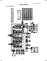
Страница 23: ... 23 FILE NO SVM 13047 1 4 WIRING DIAGRAM 4 1 RAV SP56 ATP ...
Страница 24: ... 24 FILE NO SVM 13047 4 2 RAV SP80 ATP ...
Страница 100: ... 100 FILE NO SVM 13047 1 11 1 RAV SP564ATP A 11 EXPLODED VIEWS AND PARTS LIST ...
Страница 102: ... 102 FILE NO SVM 13047 TD TS TE TO 705 708 710 704 702 701 703 711 707 712 706 Inverter assembly ...
Страница 104: ... 104 FILE NO SVM 13047 11 2 RAV SP804ATP A ...
Страница 106: ... 106 FILE NO SVM 13047 Inverter assembly 1 2 3 705 709 710 711 707 704 706 703 701 708 702 712 713 ...
Страница 109: ......

