


– 90 –
- 66 -
6
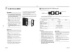
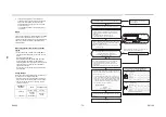
AIR PURGING
Airtight Test
Before starting an airtight test, further tighten the spindle
valves on the gas side and liquid side.
Pressurize the pipe with nitrogen gas charged from the
service port to the design pressure (4.15 MPa) to
conduct the airtight test.
After the airtight test is completed, evacuate the nitrogen
gas.
Air Purge
With respect to the preservation of the terrestrial
environment, adopt “Vacuum pump” to purge air
(Evacuate air in the connecting pipes) when installing the
unit.
• Do not discharge the refrigerant gas to the
atmosphere to preserve the terrestrial environment.
• Use a vacuum pump to discharge the air (nitrogen,
etc.) that remains in the set. If air remains, the capacity
may decrease.
For the vacuum pump, be sure to use one with a
backflow preventer so that the oil in the pump does not
backflow into the pipe of the air conditioner when the
pump stops.
(If oil in the vacuum pump is put in an air conditioner
including R410A, it may cause trouble with the
refrigeration cycle.)
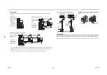
Vacuum pump
Pressure gauge
Gauge manifold valve
Handle High
(Keep fully closed)
Compound pressure gauge
Charge hose
(For R410A only)
Vacuum pump
adapter for counter-
flow prevention
(For R410A only)
–101 kPa
(–76 cmHg)
Handle Low
Charge hose
(For R410A only)
Charge port
(Valve core
(Setting pin))
Packed valve at gas side
Vacuum
pump
As shown in the figure, connect the charge hose after
the manifold valve is closed completely.
L
Attach the connecting port of the charge hose with a
projection to push the valve core (setting pin) to the
charge port of the set.
L
Open Handle Low fully.
L
Turn ON the vacuum pump. (*1)
L
Loosen the flare nut of the packed valve (Gas side) a
little to check that the air passes through. (*2)
L
Retighten the flare nut.
L
Execute vacuuming until the compound pressure
gauge indicates –101 kPa (–76 cmHg). (*1)
L
Close Handle Low completely.
L
Turn OFF the vacuum pump.
L
Leave the vacuum pump as it is for 1 or 2 minutes, and
check that the indicator of the compound pressure
gauge does not return.
L
Open the valve stem or valve handle fully. (First, at
liquid side, then gas side)
L
Disconnect the charge hose from the charge port.
L
Tighten the valve and caps of the charge port securely.
*1
Use the vacuum pump, vacuum pump adapter, and gauge
manifold correctly referring to the manuals supplied with
each tool before using them.
Check that the vacuum pump oil is filled up to the specified
line of the oil gauge.
*2
When air is not charged, check again whether the connecting
port of the discharge hose, which has a projection to push
the valve core, is firmly connected to the charge port.
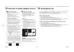
How to open the Valve
Open or close the valve.
Liquid side
Open the valve with a 4 mm hexagon wrench.
Gas side
• While the valve is fully opened, after the screwdriver
has reached the stopper, do not apply torque
exceeding 5 N•m. Applying excessive torque may
damage the valve.
Valve handling precautions
• Open the valve stem until it strikes the stopper.
It is unnecessary to apply further force.
• Securely tighten the cap with a torque wrench.
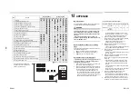
Cap tightening torque
• The cap with the 9.5 mm outer diameter is available in
two sizes in accordance with the type of packed valve
for which the cap is used. The tightening torque
depends on the width across flats of the cap so check
it in the table below.
(Unit: N•m)
Replenishing Refrigerant
This model is a 30 m chargeless type that does not need
to have its refrigerant replenished for refrigerant pipes up
to 30 m. When a refrigerant pipe longer than 30 m is
used, add the specified amount of refrigerant.
Refrigerant replenishing procedure
1.
After vacuuming the refrigerant pipe, close the
valves and then charge the refrigerant while the air
conditioner is not working.
2.
When the refrigerant cannot be charged to the
specified amount, charge the required amount of
refrigerant from the charge port of the valve on the
gas side during cooling.
Requirement for replenishing refrigerant
Replenish liquid refrigerant.
When gaseous refrigerant is replenished, the refrigerant
composition varies, which disables normal operation.
Adding additional refrigerant
• L: Pipe length
• To add additional refrigerant to twin and triple systems,
refer to the installation manual supplied with the
branching pipe (sold separately).
• The refrigerant need not be reduced for a 30 meter (or
less) refrigerant pipe.
Valve unit
Charge port
Using a minus
screwdriver, turn it
counterclockwise
by 90° until it hits
the stopper. (Full
open)
Flare nut
Handle position
Closed completely
Opened fully
Main stopper
Movable part of valve
(Stem)
Stopper pin
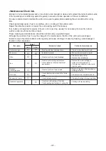
Valve size
Ø9.5 (H19 mm)
14 to 18
Ø9.5 (H22 mm)
33 to 42
Ø15.9
20 to 25
Charge port
14 to 18
31~75 m: L
40 g × (L-30)
EN-131
EN-132
Содержание RAV-SP1104AT8-E1
Страница 19: ... 19 4 WIRING DIAGRAM 4 1 Outdoor Unit RAV SP1104AT8 J E1 TR1 RAV SP1404AT8 J E1 TR1 RAV SP1604AT8 J E1 TR1 ...
Страница 113: ... 113 Outdoor Unit RAV SP1404AT8 E1 RAV SP1404AT8J E1 RAV SP1404AT8 TR1 RAV SP1404AT8J TR1 ...
Страница 117: ... 117 Outdoor Unit RAV SP1604AT8 E1 RAV SP1604AT8J E1 RAV SP1604AT8 TR1 RAV SP1604AT8J TR1 ...


