Bottom base
Do not hold the
drain socket.
Screws
Discharge port
panel
Drain pan
Drain socket
Drain socket
Handle
Connector
position
CN34
CN504
Fixing screws
Fixing screws
Entering part
Screws
Resin nut
Float switch
Drain pump
Float switch
Drain pump
Check cover
Hose band
NG
NG
No.
Part name
Procedure
Remarks
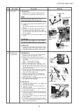
1. Detachment
1) Remove the drain cap and then extract the
drain water accumulated in the drain pan.
NOTE
When removing the drain cap, be sure to
receive drain water using a bucket, etc.
2) Loosen screws which fix the bottom base. (3
positions)
(For 140 type models, remove 2 screws at the
center.)
3) As shown in the right figure, when sliding it
toward arrow direction, the electric parts
cover the bottom base opens using the hinge
part as a shaft.
4) Hold handle of the drain pan and then pull off
slowly.
CAUTION
When removing the drain pan, do not hold the
drain socket. (Water leakage may be caused.)
2. Attachment
1) First hook the thin side of the drain pan to the
discharge panel and then push in the thick side.
2) Close the bottom base and fix it with screws.
Drain pan
i
1. Detachment
1) Perform works until opening of the electric
parts box cover in works of 1 of
f
.
2) Remove the connectors which connect to
float switch of the drain pump from the control
P.C. board.
CN34 : Float switch (3P, Red)
CN504 : Drain pump (2P, White)
3) Remove the fixing screws (2 positions) of the
check cover and then take out the check cover.
(To the check cover, the drain pump and float
switch are attached.)
4) Pick up the hose band, shift from the pump
connecting part, remove the drain hose and
then remove the check cover.
5) Remove screws which fix the drain pump
assembly and then remove the drain pump
assembly. (Ø4 x 10, 3 pcs.)
6) Remove the resin nut switch and then remove the
float switch from the fixing plate.
2. Attachment
1) Using the removed screws, fix the drain pump
assembly as original.
2) Using the removed resin nut, fix the float
switch as original.
3) Connect the drain hose as original and then
attach the hose band.
4) Connect the drain pump and the float switch
wiring as original and close the electric parts
box cover for fixing.
Be sure to perform wiring in the electric parts
box as original.
5) Enter the corners (2 positions) of the check
cover in the entering part and then fix it using
fixing screws (2 positions).
Drain pump
Float switch
j
FILE NO. SVM-18039
- 87 -
Содержание RAV-RM1101BTP Series
Страница 17: ...2 CONSTRUCTION VIEWS EXTERNAL VIEWS RAV RM561BTP RAV RM801BTP RAV RM1101BTP RAV RM1401BTP FILE NO SVM 18039 17 ...
Страница 18: ...RM56 type RM80 type RM110 RM140 type FILE NO SVM 18039 18 ...
Страница 19: ...3 WIRING DIAGRAM FILE NO SVM 18039 19 ...
Страница 34: ...5 3 Indoor Print Circuit Board MCC 1631 FILE NO SVM 18039 34 ...
Страница 89: ...11 EXPLODED VIEWS AND PARTS LIST 11 1 RAV RM561BTP E RAV RM561BTP TR FILE NO SVM 18039 89 ...
Страница 91: ...11 2 RAV RM801BTP E RAV RM801BTP TR FILE NO SVM 18039 91 ...
Страница 94: ...11 6 RAV RM1101BTP E RAV RM1101BTP TR RAV RM1401BTP E RAV RM1401BTP TR FILE NO SVM 18039 94 ...
Страница 97: ...144 9 MOO 5 BANGKADI INDUSTRIAL PARK TIVANON ROAD TAMBOL BANGKADI AMPHUR MUANG PATHUMTHANI 12000 THAILAND ...


