


CN51
CN40
SW01
Remote controller
Indoor control
P.C. board
1:1 model
connection interface
communication circuit
Terminal
resistance
1:1 model connection interface
P.C. board
MCC-1440
Indoor unit
1:1 model
connection interface
Communication units
: Total 64 units
Communication distance : 2000 m
CN050
CN041
Terminal block
(A, B)
Central controller
Indoor units in all refrigerant lines: Max. 64 units
[If mixed with SMMS (Link wiring), multi indoor units are included.]
* However group follower units of SDI, DI series are not included in number of the units.
Central control device
U1
U3
U2
U4
Central control device
U1
U3
1 2 3
U2
U4
Central control devices: Max. 10 units
Refrigerant line 1
Outdoor unit
Indoor unit
1 2 3
Refrigerant line 2
1 2 3
Refrigerant line 3
1 2 3
Refrigerant line 4
1 2 3
A B
U3 U4
Caution 3
1 2 3
A B
U3 U4
1 2 3
A B
1 2 3
A B
1 2 3
A B
1 2 3
A B
U3 U4
1:1 model connection
interface
This product
sold separately
( )
Caution 1
Remote controller
Indoor/outdoor inter-unit wire (AC230V serial)
Central control system wiring
Header unit
Header
unit
Follower
unit
Follower
unit
Follower
unit
* Wiring for No.1 and 2 only
Caution 2
Remote controller
Remote controller
Remote controller
Remote controller
wiring
Group operation (Max. 8 units)
Twin/Triple operation (Example of triple)
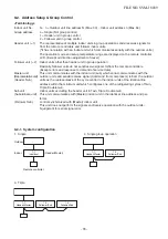
8-2. Setup at Local Site / Others
Model name: TCB-PCNT30TLE2
8-2-1. 1:1 Model Connection Interface (TCC-LINK adapter)
1. Function
This model is an optional P.C. board to connect the indoor unit to 1:1 model connection interface.
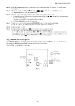
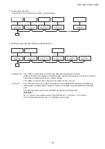
2. Microprocessor block diagram
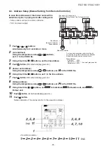
3. 1:1 model connection interface wiring connection
CAUTION
1) When controlling DI, SDI series collectively, 1:1 model connection interface (This option) is required.
2) In case of group operation, twin-triple operation, the 1:1 model connection interface is necessary to be con-
nected to the header unit.
3) Connect the central control devices to the central control system wiring.
4) When controlling DI, SDI series only, turn on only Bit 1 of SW01 of the least line of the system address No. (OFF
when shipped from the factory)
∗∗∗∗∗
In case of DI, SDI series, the address is necessary to be set up again from the wired remote
controller after automatic addressing.
FILE NO. SVM-18039
- 73 -
Содержание RAV-RM1101BTP Series
Страница 17: ...2 CONSTRUCTION VIEWS EXTERNAL VIEWS RAV RM561BTP RAV RM801BTP RAV RM1101BTP RAV RM1401BTP FILE NO SVM 18039 17 ...
Страница 18: ...RM56 type RM80 type RM110 RM140 type FILE NO SVM 18039 18 ...
Страница 19: ...3 WIRING DIAGRAM FILE NO SVM 18039 19 ...
Страница 34: ...5 3 Indoor Print Circuit Board MCC 1631 FILE NO SVM 18039 34 ...
Страница 89: ...11 EXPLODED VIEWS AND PARTS LIST 11 1 RAV RM561BTP E RAV RM561BTP TR FILE NO SVM 18039 89 ...
Страница 91: ...11 2 RAV RM801BTP E RAV RM801BTP TR FILE NO SVM 18039 91 ...
Страница 94: ...11 6 RAV RM1101BTP E RAV RM1101BTP TR RAV RM1401BTP E RAV RM1401BTP TR FILE NO SVM 18039 94 ...
Страница 97: ...144 9 MOO 5 BANGKADI INDUSTRIAL PARK TIVANON ROAD TAMBOL BANGKADI AMPHUR MUANG PATHUMTHANI 12000 THAILAND ...