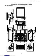
2. CONSTRUCTION VIEWS (EXTERNAL VIEWS)
2-1. RAV-
G
P561ATP
*
(D
is
char
ge
g
uide
(For di
a.8-dia
.10 ancho
r
bol
ts)
Details of A legs
250
mm or mo
re
20
0mm o
r more
10
0mm or mo
re
50
mm
Ai
r
inlet
Air inle
t port
Air o
ut
let
Space required for service
Mi
ni
mu
m
dis
tan
ce up to wall
2-d
ia.11×14 long hole
(For di
a.8-dia
.10 ancho
r
bol
t)
2-di
a.1
1×14 U-shape
hole
(Fo
r dia
.8-d
ia.10 anchor b
olt)
Eart
h termi
nal
Charge port
2-dia.11×14 U-
shape
hole
2-d
ia.11×14 long hole
Discharg
e guard
4-di
a.4
.5
embossing
D
ra
in
ho
le(di
a.2
5)
Ref
rigeran
t pipe
con
ne
cti
ng
port
(Pipin
g
dia.6.35 )
Refri
gerant pipe
co
nn
ec
ti
ng
po
rt
(Pip
ing di
a.12.7)
299
630
26
15
60
0
316
330
24
4
52
8
15
0
17
8
30
0
10
8
178
17
6
60
0
330
25
22
54
20
78
16
7
13
5
13
2
31
351
92
137
88
20
23
3
27
4
55
29
20
88
161
29
581
30
53
11
36
50
18
26
Details of B legs
6
14
8
15
R1
5
15
7
69
528
20
8
30
0
178
17
8
17
6
15
0
29
799
69
26
17
50
11
36
6
8
16
330
60
0
R1
5
di
a.
6×8
long h
ole
di
a.6
hole
di
a.6
hole
di
a.6
×
8
long hole
dia
.11
×14
long
hole
32
60
0
330
A legs
(For di
a.8-dia
.10 ancho
r
bol
t)
B legs
C L
o
r
more
moun
ting ho
le)
po
rt
6-di
a.
4.5
embossing
(P
rote
ction again
st snow hoo
d
Drain
hole
(2-di
a.2
0×88 long hole
)
po
rt
external liexternal li
nnee
ProducProduc
tt
m
ounti
ng hole)
Pa
ck
ed
va
lve
c
ove
r
FILE NO. SVM-18041
- 16 -

