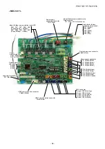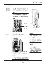
Power supply terminal block
Compressor
case thermo
UART
Compressor
lead
4-way
valve coil
IPDU
P.C. board
Reactor relay connector
Fan motor
relay connector
Earth screw
CDB fixed board
Power supply
connector
Terminal relay
connector
CDB P.C. board
UART
(CN804)
UART
(CN802)
No.
5
6
Part name
CDB P.C.
board
IPDU
P.C. board
Procedure
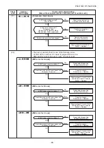
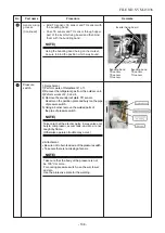
1) Perform works of Detachment 1 of
1
and 4)
of
4
.
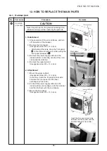
CAUTION
Never disassemble the inverter until 5 minutes
after the power supply was turned off because
there is a fear that an electric shock may occur.
2) Remove the connector and the relay connector
that are connected from CDB P.C. board to
IPDU
P.C. board, power supply and the inter-
unit
wire.
CN802: UART (5P, Blue)
CN804: UART (5P, White)
CN01: Power supply (3P, Red)
Terminal relay connector (6P, White)
∗
Unlock the lock of the housing unit and
then remove the connectors.
3) Remove the earth wire of CDB P.C. board
(Truss head B tight Ø4 × 6, 1 pc.)
4) Remove CDB P.C. board from CDB fixed
board.
5) Mount a new CDB P.C. board.
∗
When connecting the connectors on CDB
P.C. board to support CDB fixed board with
hand.
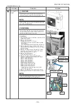
1) Perform works of Detachment 1 of
1
, 3) of
2
,
4
and 2), 3) of
5
.
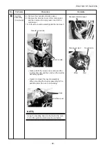
CAUTION
Never disassemble the inverter until 5 minutes
after the power supply was turned off because
there is a fear that an electric shock may occur.
2) Take off screw for CDB fixed board and the
inverter box. (ST1T Ø4 × 8, 1 pc.)
3) Remove CDB P.C. board assembly.
4) Remove the connectors connected to
IPDU
P.C.
board. (4-way valve coil, compressor
case
thermo, UART × 2, Inter-unit wire)
5) Remove the relay connector for fan
motor
,
reactor
, and High pressure switch.
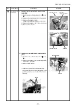
6) Remove the lead wire connected to
IPDU
P.C.
board.
(Tightening torque: 1.47 ± 0.1 N•m)
U : CN200, Red
V : CN201, White
W : CN202, Black
Remove the power supply cable from the
power supply terminal block.
Power supply lead L: Red
Power supply lead N: White
Remarks
High pressure switch relay connector
Compressor lead
FILE NO. SVM-15036
- 99 -
Содержание RAS-5M34S3AV-A
Страница 112: ......


