10-
2
-
5
.
Electrical Work
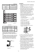
For the air conditioner that has no power cord,
connect a power cord to it as mentioned below.
Model
Power supply
Maximum running current
Installation fuse rating
Power cord
4
Units Multi
RAS-
4
M2
7
U2AVG-E
,-TR
220 – 240 V, ~50 Hz
1
6
.4
A
20 A breaker of fuse
(All types can be used.)
H07 RN-F or 245 IEC 66
(2.5 mm²
or more)
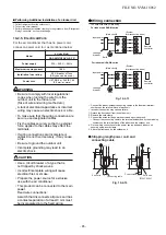
Wiring connection
Stripping length power cord and
connecting cable
Fig. 10-2-1
4
■
Performing Additional Installation of an Indoor Unit
1. Collect refrigerant from the outdoor unit.
2. Turn off the circuit breaker.
3. Perform additional installation referring to the procedure from “Refrigerant
Piping Connection” on the previous page.
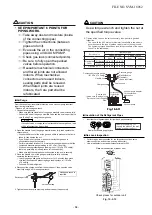
WARNING
•
•
•
•
•
Be sure to comply with local regulations/
codes when running the wire from the
outdoor unit to the indoor unit.
(Size of wire and wiring method etc.)
A lack of electrical capacitance or incorrect
wiring may cause an electric shock or a
fi
re.
To make sure that the wiring connection
are
secure, use designated cables.
Fix the cables securely so that no external
force applied to the cables may effect the
terminals.
If wiring connections are incomplete or
cables are not
fixed securely, it may cause
a fire.
• Be sure to ground the outdoor unit.
• Incomplete grounding may lead to an
electric shock.
CAUTION
•
•
•
Use a circuit breaker of a type that is
not
tripped by shock waves.
Incorrect/incomplete wiring will cause
electrical
fires or smoke.
Prepare the power source for exclusive
use with the air conditioner.
• This product can be connected to the main
power.
Fixed wire connections:
A switch that disconnects all poles and has
a contact separation of at least 3 mm
must
be incorporated into the
fixed
wiring.
2
L
N
3
1
2
3
2
L
N
3
2
3
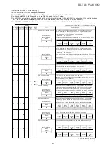
• The dash lines show on-site wiring.
For indoor unit RAS-M series.
Earth
For indoor unit RAS-B series.
(Main circuit)
(Main circuit)
Input power
Input power
(System
interconnection wires)
(System
interconnection wires)
Leakage
breaker
Leakage
breaker
Remote
controller
Remote
controller
Indoor unit
Indoor unit
Earth
• Connect the indoor/outdoor connecting cables to the identical terminal
numbers on the terminal block of each unit.
• Incorrect connection may cause a failure.
1.
Detach the front panel from the outdoor unit.
2.
Remove the cord clamp.
3.
Connect the wires for the power source and each indoor unit.
• Connect the connecting cable to the terminal as identi
fi
ed
by
the matching
numbers on the terminal block of the indoor and the outdoor unit.
4.
Fix the wiring connections for the power source and each indoor unit
securely using a cord clamp.
5.
Attach the front panel to the outdoor unit.
55
5
5
30
1
(L)
2 3
5
5
30
55
L N
Earth wire
Earth wire
(Unit : mm)
Power cord
Connecting cable
Fig. 10-2-
1
3
FILE NO. SVM-18052
- 65 -


