background image

SERVICE MANUAL

FILE  NO.  A01-004

AIR-CONDITIONER

SPLIT TYPE

PRINTED IN JAPAN, Mar.,2001   ToMo 

RAS-M10YKV-E, RAS-M13YKV-E, RAS-M16YKV-E

RAS-4M27YAV-E

RAS-M10YKCV-E, RAS-M13YKCV-E, RAS-M16YKCV-E

RAS-4M27YACV-E

RAS-M10YKV-E, RAS-M13YKV-E, RAS-M16YKV-E

RAS-3M26YAV-E

R410A

• Indoor Unit (1)

• Indoor Unit (2)

• Outdoor Unit

• P.C. board Layout

   RAS-4M27YAV-E
   RAS-4M27YACV-E
   RAS-3M26YAV-E

Parts List 

F i l e   N o .   A 0 1 - 0 0 4

Содержание RAS-3M26YAV-E

Страница 1: ...Mo RAS M10YKV E RAS M13YKV E RAS M16YKV E RAS 4M27YAV E RAS M10YKCV E RAS M13YKCV E RAS M16YKCV E RAS 4M27YACV E RAS M10YKV E RAS M13YKV E RAS M16YKV E RAS 3M26YAV E R410A Indoor Unit 1 Indoor Unit 2 Outdoor Unit P C board Layout RAS 4M27YAV E RAS 4M27YACV E RAS 3M26YAV E Parts List File No A01 004 ...

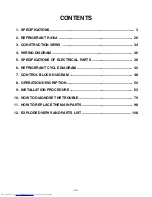
Страница 2: ...4 WIRING DIAGRAM 36 5 SPECIFICATIONS OF ELECTRICAL PARTS 38 6 REFRIGERANT CYCLE DIAGRAM 40 7 CONTROL BLOCK DIAGRAM 48 8 OPERATION DESCRIPTION 50 9 INSTALLATION PROCEDURE 63 10 HOW TO DIAGNOSE THE TROUBLE 79 11 HOW TO REPLACE THE MAIN PARTS 98 12 EXPLODED VIEWS AND PARTS LIST 108 ...

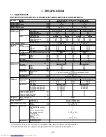
Страница 3: ...3YKV E RAS M16YKV E Height mm 265 265 265 Width mm 790 790 790 Dimension Depth mm 189 189 189 Net weight kg 8 8 8 Fan motor output W 19 19 19 Indoor unit Air flow rate Cooling Heating m h 470 520 520 560 600 600 Unit model RAS 4M27YAV E RAS 3M26YAV E Height mm 795 795 Width mm 900 900 Dimension Depth mm 320 320 Net weight kg 65 64 Motor output W 2000 Type Twin rotary type with DC inverter variable...

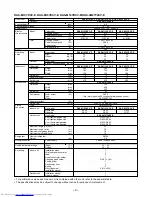
Страница 4: ... W 19 19 19 Indoor unit Air flow rate m h 470 520 600 Unit model RAS 4M27YACV E Height mm 795 Width mm 900 Dimension Depth mm 320 Net weight kg 63 Motor output W 2000 Type Twin rotary type with DC inverter variable speed control Compressor Model DA220A2F 20L Fan motor output W 60 Outdoor unit Air flow rate m h High 3000 Medium 2800 Type Flare connection Unit model RAS M10YKCV E RAS M13YKCV E RAS M...

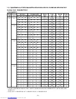
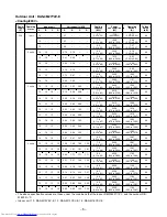
Страница 5: ...o 12 71 48 16 10 10 3 50 2 10 2 10 7 7 4 0 to 8 5 2410 960 to 2790 11 18 4 85 to 12 94 48 13 13 10 2 82 2 82 2 06 7 7 4 0 to 8 5 2410 960 to 2790 11 18 4 85 to 12 94 48 16 13 10 3 22 2 65 1 93 7 8 4 1 to 8 6 2430 970 to 2810 11 27 4 90 to 13 03 48 13 13 13 2 60 2 60 2 60 7 8 4 1 to 8 6 2430 970 to 2810 11 27 4 90 to 13 03 48 16 16 10 3 04 3 04 1 82 7 9 4 1 to 8 7 2440 970 to 2830 11 32 4 90 to 13 ...

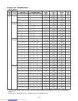
Страница 6: ... to 8 5 2410 960 to 2790 10 69 4 64 to 12 38 48 13 13 10 2 82 2 82 2 06 7 7 4 0 to 8 5 2410 960 to 2790 10 69 4 64 to 12 38 48 16 13 10 3 22 2 65 1 93 7 8 4 1 to 8 6 2430 970 to 2810 10 78 4 69 to 12 47 48 13 13 13 2 60 2 60 2 60 7 8 4 1 to 8 6 2430 970 to 2810 10 78 4 69 to 12 47 48 16 16 10 3 04 3 04 1 82 7 9 4 1 to 8 7 2440 970 to 2830 10 83 4 69 to 12 56 48 16 13 13 2 99 2 46 2 46 7 9 4 1 to 8...

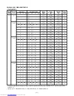
Страница 7: ... to 8 5 2410 960 to 2790 10 25 4 44 to 11 86 48 13 13 10 2 82 2 82 2 06 7 7 4 0 to 8 5 2410 960 to 2790 10 25 4 44 to 11 86 48 16 13 10 3 22 2 65 1 93 7 8 4 1 to 8 6 2430 970 to 2810 10 33 4 49 to 11 95 48 13 13 13 2 60 2 60 2 60 7 8 4 1 to 8 6 2430 970 to 2810 10 33 4 49 to 11 95 48 16 16 10 3 04 3 04 1 82 7 9 4 1 to 8 7 2440 970 to 2830 10 37 4 49 to 12 03 48 16 13 13 2 99 2 46 2 46 7 9 4 1 to 8...

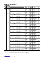
Страница 8: ... 0 to 10 5 2350 380 to 2760 10 90 2 16 to 12 80 48 13 13 10 3 11 3 11 2 49 8 7 2 0 to 10 5 2350 380 to 2760 10 90 2 16 to 12 80 48 16 13 10 3 34 3 03 2 43 8 8 2 0 to 10 6 2400 380 to 2780 11 13 2 16 to 12 89 48 13 13 13 2 93 2 93 2 93 8 8 2 0 to 10 6 2400 380 to 2780 11 13 2 16 to 12 89 48 16 16 10 3 26 3 26 2 37 8 9 2 0 to 10 7 2450 380 to 2790 11 36 2 16 to 12 94 48 16 13 13 3 16 2 87 2 87 8 9 2...

Страница 9: ...7 2 0 to 10 5 2350 380 to 2760 10 43 2 07 to 12 24 48 13 13 10 3 11 3 11 2 49 8 7 2 0 to 10 5 2350 380 to 2760 10 43 2 07 to 12 24 48 16 13 10 3 34 3 03 2 43 8 8 2 0 to 10 6 2400 380 to 2780 10 65 2 07 to 12 33 48 13 13 13 2 93 2 93 2 93 8 8 2 0 to 10 6 2400 380 to 2780 10 65 2 07 to 12 33 48 16 16 10 3 26 3 26 2 37 8 9 2 0 to 10 7 2450 380 to 2790 10 87 2 07 to 12 38 48 16 13 13 3 16 2 87 2 87 8 ...

Страница 10: ...7 2 0 to 10 5 2350 380 to 2760 9 99 1 98 to 11 73 48 13 13 10 3 11 3 11 2 49 8 7 2 0 to 10 5 2350 380 to 2760 9 99 1 98 to 11 73 48 16 13 10 3 34 3 03 2 43 8 8 2 0 to 10 6 2400 380 to 2780 10 20 1 98 to 11 82 48 13 13 13 2 93 2 93 2 93 8 8 2 0 to 10 6 2400 380 to 2780 10 20 1 98 to 11 82 48 16 16 10 3 26 3 26 2 37 8 9 2 0 to 10 7 2450 380 to 2790 10 42 1 98 to 11 86 48 16 13 13 3 16 2 87 2 87 8 9 ...

Страница 11: ...4 0 to 8 5 2410 960 to 2790 11 18 4 85 to 12 94 48 13 13 10 2 82 2 82 2 06 7 7 4 0 to 8 5 2410 960 to 2790 11 18 4 85 to 12 94 48 16 13 10 3 22 2 65 1 93 7 8 4 1 to 8 6 2430 970 to 2810 11 27 4 90 to 13 03 48 13 13 13 2 60 2 60 2 60 7 8 4 1 to 8 6 2430 970 to 2810 11 27 4 90 to 13 03 48 16 16 10 3 04 3 04 1 82 7 9 4 1 to 8 7 2440 970 to 2830 11 32 4 90 to 13 13 48 16 13 13 2 99 2 46 2 46 7 9 4 1 t...

Страница 12: ...4 0 to 8 5 2410 960 to 2790 10 69 4 64 to 12 38 48 13 13 10 2 82 2 82 2 06 7 7 4 0 to 8 5 2410 960 to 2790 10 69 4 64 to 12 38 48 16 13 10 3 22 2 65 1 93 7 8 4 1 to 8 6 2430 970 to 2810 10 78 4 69 to 12 47 48 13 13 13 2 60 2 60 2 60 7 8 4 1 to 8 6 2430 970 to 2810 10 78 4 69 to 12 47 48 16 16 10 3 04 3 04 1 82 7 9 4 1 to 8 7 2440 970 to 2830 10 83 4 69 to 12 56 48 16 13 13 2 99 2 46 2 46 7 9 4 1 t...

Страница 13: ... 0 to 8 5 2410 960 to 2790 10 25 4 44 to 11 86 48 13 13 10 2 82 2 82 2 06 7 7 4 0 to 8 5 2410 960 to 2790 10 25 4 44 to 11 86 48 16 13 10 3 22 2 65 1 93 7 8 4 1 to 8 6 2430 970 to 2810 10 33 4 49 to 11 95 48 13 13 13 2 60 2 60 2 60 7 8 4 1 to 8 6 2430 970 to 2810 10 33 4 49 to 11 95 48 16 16 10 3 04 3 04 1 82 7 9 4 1 to 8 7 2440 970 to 2830 10 37 4 49 to 12 03 48 16 13 13 2 99 2 46 2 46 7 9 4 1 to...

Страница 14: ...00 9 46 3 81 to 11 13 48 13 13 3 15 3 15 6 3 2 9 to 6 9 2040 670 to 2400 9 46 3 81 to 11 13 48 16 13 3 73 3 07 6 8 3 0 to 7 2 2320 690 to 2570 10 76 3 92 to 11 92 48 16 16 3 60 3 60 7 2 3 2 to 7 5 2550 700 to 2750 11 83 3 98 to 12 76 48 3 units 10 10 10 2 47 2 47 2 47 7 4 3 8 to 8 2 2230 950 to 2720 10 34 4 80 to 12 62 48 13 10 10 3 01 2 20 2 20 7 4 3 9 to 8 3 2230 950 to 2750 10 34 4 80 to 12 76 ...

Страница 15: ...o 2400 9 05 3 64 to 10 65 48 13 13 3 15 3 15 6 3 2 9 to 6 9 2040 670 to 2400 9 05 3 64 to 10 65 48 16 13 3 73 3 07 6 8 3 0 to 7 2 2320 690 to 2570 10 29 3 75 to 11 40 48 16 16 3 60 3 60 7 2 3 2 to 7 5 2550 700 to 2750 11 31 3 80 to 12 20 48 3 units 10 10 10 2 47 2 47 2 47 7 4 3 8 to 8 2 2230 950 to 2720 9 89 4 59 to 12 07 48 13 10 10 3 01 2 20 2 20 7 4 3 9 to 8 3 2230 950 to 2750 9 89 4 59 to 12 2...

Страница 16: ...o 2400 8 67 3 49 to 10 20 48 13 13 3 15 3 15 6 3 2 9 to 6 9 2040 670 to 2400 8 67 3 49 to 10 20 48 16 13 3 73 3 07 6 8 3 0 to 7 2 2320 690 to 2570 9 86 3 59 to 10 93 48 16 16 3 60 3 60 7 2 3 2 to 7 5 2550 700 to 2750 10 84 3 65 to 11 69 48 3 units 10 10 10 2 47 2 47 2 47 7 4 3 8 to 8 2 2230 950 to 2720 9 48 4 40 to 11 56 48 13 10 10 3 01 2 20 2 20 7 4 3 9 to 8 3 2230 950 to 2750 9 48 4 40 to 11 69...

Страница 17: ... 11 04 1 94 to 14 98 48 13 13 3 95 3 95 7 9 1 5 to 10 1 2380 320 to 3230 11 04 1 94 to 14 98 48 16 13 4 35 3 95 8 3 1 5 to 10 2 2560 320 to 3240 11 87 1 94 to 15 03 48 16 16 4 30 4 30 8 6 1 5 to 10 2 2700 320 to 3250 12 52 1 94 to 15 07 48 3 units 10 10 10 2 87 2 87 2 87 8 6 2 0 to 10 4 2300 380 to 2750 10 67 2 16 to 12 76 48 13 10 10 3 35 2 68 2 68 8 7 2 0 to 10 5 2360 380 to 2760 10 95 2 16 to 1...

Страница 18: ... 10 56 1 86 to 14 33 48 13 13 3 95 3 95 7 9 1 5 to 10 1 2380 320 to 3230 10 56 1 86 to 14 33 48 16 13 4 35 3 95 8 3 1 5 to 10 2 2560 320 to 3240 11 36 1 86 to 14 37 48 16 16 4 30 4 30 8 6 1 5 to 10 2 2700 320 to 3250 11 98 1 86 to 14 42 48 3 units 10 10 10 2 87 2 87 2 87 8 6 2 0 to 10 4 2300 380 to 2750 10 20 2 07 to 12 20 48 13 10 10 3 35 2 68 2 68 8 7 2 0 to 10 5 2360 380 to 2760 10 47 2 07 to 1...

Страница 19: ... 10 12 1 78 to 13 73 48 13 13 3 95 3 95 7 9 1 5 to 10 1 2380 320 to 3230 10 12 1 78 to 13 73 48 16 13 4 35 3 95 8 3 1 5 to 10 2 2560 320 to 3240 10 88 1 78 to 13 78 48 16 16 4 30 4 30 8 6 1 5 to 10 2 2700 320 to 3250 11 48 1 78 to 13 82 48 3 units 10 10 10 2 87 2 87 2 87 8 6 2 0 to 10 4 2300 380 to 2750 9 78 1 98 to 11 69 48 13 10 10 3 35 2 68 2 68 8 7 2 0 to 10 5 2360 380 to 2760 10 03 1 98 to 11...

Страница 20: ...100 95 90 85 80 0 10 20 30 40 50 60 70 80 Total pipe length m Coolimg capacity ratio Conditions Indoor DB27 C WB19 C Outdoor DB35 C Indoor air flow High 4 units operating Standard pipe length 20m 110 105 100 95 90 85 80 0 10 20 30 40 50 60 70 80 Total pipe length m Heating capacity ratio Conditions Indoor DB20 C Outdoor DB7 C WB6 C Indoor air flow High 4 units operating Standard pipe length 20m 50...

Страница 21: ... 83 0 15 x 3 0 45 0 5 16 16 10 13 30 13 30 20 9 88 9 88 0 15 x 3 0 45 0 5 16 13 13 13 30 13 30 20 9 88 9 88 0 15 x 3 0 45 0 5 16 16 13 13 30 13 30 20 9 88 9 88 0 15 x 3 0 45 0 5 3 units 16 16 16 13 35 13 35 20 9 92 9 92 0 15 x 3 0 45 0 5 10 10 10 10 13 31 13 31 20 9 77 9 77 0 15 x 4 0 60 0 5 13 10 10 10 13 31 13 31 20 9 77 9 77 0 15 x 4 0 60 0 5 16 10 10 10 13 59 13 59 20 9 99 9 99 0 15 x 4 0 60 0...

Страница 22: ...0 0 15 x 3 0 45 0 5 16 16 10 13 35 13 35 20 9 92 9 92 0 15 x 3 0 45 0 5 16 13 13 13 35 13 35 20 9 92 9 92 0 15 x 3 0 45 0 5 16 16 13 13 35 13 35 20 9 92 9 92 0 15 x 3 0 45 0 5 3 units 16 16 16 13 63 13 63 20 10 14 10 14 0 15 x 3 0 45 0 5 10 10 10 10 11 38 11 38 20 8 22 8 22 0 15 x 4 0 60 0 5 13 10 10 10 11 38 11 38 20 8 22 8 22 0 15 x 4 0 60 0 5 16 10 10 10 12 20 12 20 20 8 88 8 88 0 15 x 4 0 60 0...

Страница 23: ...3 0 45 0 5 16 16 10 13 30 13 30 20 9 88 9 88 0 15 x 3 0 45 0 5 16 13 13 13 30 13 30 20 9 88 9 88 0 15 x 3 0 45 0 5 16 16 13 13 30 13 30 20 9 88 9 88 0 15 x 3 0 45 0 5 3 units 16 16 16 13 35 13 35 20 9 92 9 92 0 15 x 3 0 45 0 5 10 10 10 10 13 31 13 31 20 9 77 9 77 0 15 x 4 0 60 0 5 13 10 10 10 13 31 13 31 20 9 77 9 77 0 15 x 4 0 60 0 5 16 10 10 10 13 59 13 59 20 9 99 9 99 0 15 x 4 0 60 0 5 13 13 10...

Страница 24: ... 8 94 8 94 0 15 x 3 0 45 0 5 13 10 10 12 13 12 13 20 8 94 8 94 0 15 x 3 0 45 0 5 16 10 10 12 13 12 13 20 8 94 8 94 0 15 x 3 0 45 0 5 13 13 10 12 13 12 13 20 8 94 8 94 0 15 x 3 0 45 0 5 16 13 10 12 24 12 24 20 9 03 9 03 0 15 x 3 0 45 0 5 13 13 13 12 24 12 24 20 9 03 9 03 0 15 x 3 0 45 0 5 16 16 10 12 24 12 24 20 9 03 9 03 0 15 x 3 0 45 0 5 16 13 13 12 24 12 24 20 9 03 9 03 0 15 x 3 0 45 0 5 3 units...

Страница 25: ...5 1 unit 16 13 15 13 15 20 10 00 10 00 0 15 x 1 0 15 0 5 10 10 11 16 11 16 20 8 29 8 29 0 15 x 2 0 30 0 5 13 10 12 23 12 23 20 9 14 9 14 0 15 x 2 0 30 0 5 16 10 13 00 13 00 20 9 76 9 76 0 15 x 2 0 30 0 5 13 13 13 00 13 00 20 9 76 9 76 0 15 x 2 0 30 0 5 16 13 14 00 14 00 20 10 56 10 56 0 15 x 2 0 30 0 5 2 units 16 16 14 78 14 78 20 11 18 11 18 0 15 x 2 0 30 0 5 10 10 10 12 51 12 51 20 9 25 9 25 0 1...

Страница 26: ...e pressure in the refrigeration cycle may become abnormally high so that a rupture or personal injury may be caused 5 After completion of installation work check to make sure that there is no refrigeration gas leakage If the refrigerant gas leaks into the room coming into contact with fire in the fan driven heater space heater etc a poisonous gas may occur 6 When an air conditioning system charged...

Страница 27: ...thicknesses of socket joints Nominal diameter 1 4 3 8 1 2 Reference outer diameter of copper pipe jointed mm 6 35 9 52 12 70 Minimum joint thickness mm 0 50 0 60 0 70 2 2 2 Processing of Piping Materials When performing the refrigerant piping installation care should be taken to ensure that water or dust does not enter the pipe interior that no other oil other than lubricating oils used in the ins...

Страница 28: ...2 12 70 Thickness mm 0 8 0 8 0 8 A mm Flare tool for Conventional flare tool R410A clutch type Clutch type Wing nut type 0 to 0 5 1 0 to 1 5 1 5 to 2 0 0 to 0 5 1 0 to 1 5 1 5 to 2 0 0 to 0 5 1 0 to1 5 2 0 to 2 5 Table 2 2 4 Dimensions related to flare processing for R22 Nominal diameter 1 4 3 8 1 2 Outer diameter mm 6 35 9 52 12 70 Thickness mm 0 8 0 8 0 8 A mm Flare tool for Conventional flare t...

Страница 29: ...hat for conventional R22 Incidentally when the torque is weak the gas leakage may occur When it is strong the flare nut may crack and may be made non removable When choos ing the tightening torque comply with values designated by manufacturers Table 2 2 7 shows reference values Note When applying oil to the flare surface be sure to use oil designated by the manufacturer If any other oil is used th...

Страница 30: ...igerant charging Refrigerant cylinder Leakage detector Charging cylinder Usage Pipe flaring Flaring by conventional flare tool Connection of flare nut Evacuating refrigerant charge run check etc Vacuum evacuating Refrigerant charge Refrigerant charge Gas leakage check Refrigerant charge R410A air conditioner installation Existence of Whether conventional new equipment for R410A equipment can be us...

Страница 31: ...nsure that the compound gauge s pointer does not return Set the refrigerant cylinder to the electronic balance connect the connecting hose to the cylinder and the connecting port of the electronic balance and charge liquid refrigerant Q Never charge refrigerant exceeding the specified amount R If the specified amount of refrigerant cannot be charged charge refrigerant bit by bit in COOL mode S Do ...

Страница 32: ...hor bronze brazing filler is generally used to join copper or copper alloy 3 Low temperature brazing filler Low temperature brazing filler is generally called solder and is an alloy of tin and lead Since it is weak in adhesive strength do not use it for refrigerant pipes Q Phosphor bronze brazing filler tends to react with sulfur and produce a fragile compound water solution which may cause a gas ...

Страница 33: ...the pipe the lubricating oil deterio rates Therefore use a flux which does not contain chlorine S When adding water to the flux use water which does not contain chlorine e g distilled water or ion exchange water T Remove the flux after brazing 2 5 3 Brazing As brazing work requires sophisticated techniques experiences based upon a theoretical knowledge it must be performed by a person qualified In...

Страница 34: ...ting pipe 0 39m Flare Ø6 35 Flare Ø9 52 RAS M10YKV E RAS M10YKCV E RAS M13YKV E RAS M13YKCV E Flare Ø12 7 RAS M16YKV E RAS M16YKCV E Hanger 659 65 5 326 450 65 5 For stud bolt Ø8 to Ø10 For stud bolt Ø6 Hanger Minimum distance to wall Minimum distance to ceiling 265 178 5 Knock out system Front panel Back body 20 20 37 40 5 60 5 790 126 269 319 76 10 5 Center line Installation plate outline Hanger...

Страница 35: ...0hole Anchor bolt 4 Ø12 x 17 hole 280 40 19 12 86 12 21 12 120 25 95 320 Z Liquid valve Gas valve Service port 164 91 514 38 53 53 53 53 53 90 53 53 58 40 40 87 116 Z 600 365 100 or more 600 or more Air inlet 100 or more 600 or more Air inlet Air outlet Visible outline of the product view Ø8 Ø10 anchor bolt Mounting dimension of anchor bolt Connecting pipe port Ø6 35 Connecting pipe port Ø9 52 C u...

Страница 36: ...it Check for voltage at the CN10 connector side point Check the transformer and the rated voltage power supply circuit For detailed diagnostic procedure refer to the service data DSA Surge Absorber Check items OPERATION indicator Terminal block Fuse 6 3A DC 5V DC 12V DC 35V MAIN P C BOARD MCC 772 BLK P04 CN30 CN23 CN31 INDOOR TERMINAL BLOCK INDOOR UNIT OUTDOOR UNIT CN07 CN10 TO1 DC35V DC12V DC7V D...

Страница 37: ...o Indoor unit B 1 2 3 To Indoor unit C 1 2 3 To Indoor unit D Power supply 50 60Hz AC 220 240V 2 1 2 1 TE CN604 2 1 2 1 TS CN603 3 2 1 3 1 TGa 3 2 1 3 1 YEL BLU BLK CN606 TGb 3 2 1 3 1 BRN GRY ORN BLU YEL BZ BY BX EW BW EV BV EU BU CN09 CN10 CN11 CN607 TGc 3 2 1 3 1 GRN CN608 TGd 2 1 2 1 BLU BLK WHI RED RED Compressor Fan motor 4 way valve coil 3 1 3 1 3 1 3 1 BLU YEL 2 1 2 1 2 1 2 1 2 1 2 1 PUR O...

Страница 38: ...DC transformer T01 SWT 34 DC 390V Secondary DC 35V 12V 7V 4 Microcomputer TMP87CM40AF 5 Heat exchanger sensor 10kΩ at 25 C TC sensor 6 Line filter L01 UF 253Y0R7 25mH AC 0 7A 7 Diode DB01 RBV 406 or D3SBA60 4A 600V 8 Capacitor C02 KMH450VNSN100M25B 100µF 450V 9 Fuse F01 TSCR6 3A T6 3A 250V 10 Power supply IC IC01 MA2830P FJ 8A 850V 11 Varistor R21 R109 15G561K 560V 12 Resistor R01 ERF 5TK5R6 5 6Ω ...

Страница 39: ...Inverter attached Inverter attached Inverter attached Inverter attached Inverter attached For protection of switching power source F04 For protection of converter module breakage For protection of inverter input overcurrent For protection of switching power source F300 For protection of power source LLQ2G761KHUATF 6MBI40SS 060 01 DA220A2F 20L US622KXTMQO MP7004 CH 47 Z K CH 43 Z K Rating AC2 50V 2...

Страница 40: ...d TGc TGb Per 1 unit Max 25m Min 2m Total Max 70m Ø6 35 Ø9 52 Ø9 52 Ø9 52 Ø12 7 Ø6 35 Ø6 35 Ø6 35 Pulse modulating valve at liquid side SKV18D26 Refrigerant amount 2 4kg R410A NOTE Gas leak check position Refrigerant flow Cooling Refrigerant flow Heating Temp measurement Pressure measurement Gauge attaching port Vacuum pump connecting port Sectional shape of heat insulator Connecting pipe Thicknes...

Страница 41: ...in 2m Total Max 70m Ø6 35 Ø9 52 Ø9 52 Ø9 52 Ø12 7 Ø6 35 Ø6 35 Ø6 35 Pulse modulating valve at liquid side SKV18D26 Refrigerant amount 2 2kg R410A NOTE Gas leak check position Refrigerant flow Temp measurement Pressure measurement Gauge attaching port Vacuum pump connecting port Sectional shape of heat insulator Connecting pipe Thickness 0 8mm Ø6 35 Temp measurement TD Accumulating tank 1500cc TA R...

Страница 42: ... 50m Ø6 35 Ø9 52 Ø9 52 Ø12 7 Ø6 35 Ø6 35 TS Pulse modulating valve at liquid side SKV18D26 Refrigerant amount 2 4kg R410A NOTE Gas leak check position Refrigerant flow Cooling Refrigerant flow Heating Temp measurement Pressure measurement Gauge attaching port Vacuum pump connecting port Sectional shape of heat insulator Connecting pipe Thickness 0 8mm Ø6 35 Temp measurement TA Accumulating tank 15...

Страница 43: ...54 16 13 0 7 to 0 9 9 to 11 51 to 53 High MED 58 2 units 16 16 0 7 to 0 9 9 to 11 52 to 54 High MED 62 10 10 10 0 8 to 1 0 11 to 13 51 to 53 High MED 60 13 10 10 0 8 to 1 0 11 to 13 51 to 53 High MED 60 16 10 10 0 8 to 1 0 11 to 13 51 to 53 High MED 60 13 13 10 0 8 to 1 0 11 to 13 51 to 53 High MED 60 16 13 10 0 8 to 1 0 11 to 13 51 to 53 High MED 60 13 13 13 0 8 to 1 0 11 to 13 51 to 53 High MED ...

Страница 44: ...h MED 67 16 13 3 0 to 3 2 47 to 49 1 to 1 High MED 69 2 units 16 16 3 1 to 3 3 48 to 50 1 to 1 High MED 71 10 10 10 2 3 to 2 5 38 to 40 1 to 1 High MED 72 13 10 10 2 3 to 2 5 38 to 40 1 to 1 High MED 72 16 10 10 2 3 to 2 5 38 to 40 1 to 1 High MED 72 13 13 10 2 3 to 2 5 38 to 40 1 to 1 High MED 73 16 13 10 2 3 to 2 5 38 to 40 1 to 1 High MED 73 13 13 13 2 3 to 2 5 38 to 40 1 to 1 High MED 73 16 16...

Страница 45: ...3 0 7 to 0 9 9 to 11 51 to 53 High MED 58 2 units 16 16 0 7 to 0 9 9 to 11 52 to 54 High MED 62 10 10 10 0 8 to 1 0 11 to 13 51 to 53 High MED 60 13 10 10 0 8 to 1 0 11 to 13 51 to 53 High MED 60 16 10 10 0 8 to 1 0 11 to 13 51 to 53 High MED 60 13 13 10 0 8 to 1 0 11 to 13 51 to 53 High MED 60 16 13 10 0 8 to 1 0 11 to 13 51 to 53 High MED 60 13 13 13 0 8 to 1 0 11 to 13 51 to 53 High MED 60 16 1...

Страница 46: ...nit 16 0 6 to 0 8 7 to 9 47 to 49 High MED 45 10 10 0 8 to 1 0 10 to 12 47 to 49 High MED 42 13 10 0 8 to 1 0 10 to 12 48 to 50 High MED 46 16 10 0 8 to 1 0 10 to 12 49 to 51 High MED 50 13 13 0 8 to 1 0 10 to 12 50 to 51 High MED 54 16 13 0 7 to 0 9 9 to 11 51 to 53 High MED 58 2 units 16 16 0 7 to 0 9 9 to 11 52 to 54 High MED 62 10 10 10 0 8 to 1 0 11 to 13 51 to 53 High MED 60 13 10 10 0 8 to ...

Страница 47: ...igh MED 50 1 unit 16 3 5 to 3 7 55 to 57 1 to 3 High MED 53 10 10 2 7 to 2 9 45 to 47 0 to 2 High MED 62 13 10 2 8 to 3 0 45 to 47 0 to 2 High MED 63 16 10 2 9 to 3 1 46 to 48 0 to 2 High MED 65 13 13 2 9 to 3 1 46 to 48 0 to 2 High MED 66 16 13 3 1 to 3 3 47 to 49 0 to 2 High MED 68 2 units 16 16 3 3 to 3 5 50 to 52 0 to 2 High MED 70 10 10 10 2 3 to 2 5 38 to 40 1 to 1 High MED 72 13 10 10 2 3 t...

Страница 48: ...Receiver Initializing Circuit Clock Frequency Oscillator Circuit Power Supply Circuit Infrared Rays Remote Controller RAS M10YKV E RAS M13YKV E RAS M16YKV E Heat pump model RAS M10YKCV E RAS M13YKCV E RAS M16YKCV E Cooling only model Operation START STOP Thermo Setting Fan Speed Selection ON TIMER Setting OFF TIMER Setting Louver AUTO Swing Louver Direction Setting ECONO Operation Mode Selection A...

Страница 49: ...ut current release control A D converter function M C U DSP Discharge temp Sensor Gas side pipe temp Sensor Suction temp Sensor Evaporator temp Sensor Outdoor air temp Sensor MCC 818 SUB P C B MCC 1359 MAIN P C B 220 240V 50 60Hz Driver circuit of P M V Signal communication to MCU Inverter DC AC Over current sensor Compressor B unit P M V C unit P M V D unit P M V 4 Way valve Relay circuit Noise f...

Страница 50: ...r sensor Prevent freezing control Louver motor control Indoor fan motor operation control LED display control Transferring of operation command signal Serial signal to the outdoor unit Reception of information of operation status Serial signal including outside temp data to the outdoor unit and judgment display of error Operations followed to judgment of serial signal from indoor side 2 Role of ou...

Страница 51: ...d value the outdoor main circuit control section controls compressor motor speed by reduc ing motor speed so that value becomes closest to the command within the limited value Table 8 1 1 Compressor revolution range Operation mode COOL Combination of indoor units M10 M13 M16 In case that any multiple indoor units are combined Compressor revolution rps 20 to 28 20 to 43 20 to 53 20 to 66 31 to 69 3...

Страница 52: ...ing running operation vertical air flow louvers start swinging When the AUTO button is pressed again swinging stops 8 1 7 Indoor Fan Control DC Fan Motor The indoor fan is operated by motor speed non step variable DC drive system motor For flow rate motor speed is controlled manually in three steps LOW MED HIGH and with the unit of 10 rpm from upper limit to lower limit in AUTO mode as described i...

Страница 53: ...it Turning ON the breaker flashes the operation lamp This is the display of power ON or notification of power failure When pushing START STOP button of the remote controller receive sound is issued from the main unit and the next operations are performed together with opening the vertical air flow louvers Compressor revolution rps Outdoor temp sensor TO 5 C TO TO 5 C ECONO operation TO 5 C TO 5 C ...

Страница 54: ...eed 11 5A if current value exceeds 11 5A When the current value lowers to 11 0A return the operation to the above item 1 Normal control 14 2 13 7 Current value Comp motor speed down Comp motor speed keep Fig 8 2 3 4 Outdoor temperature release control The outdoor temperature release is controlled by changing the current release points 14 2 and 13 7 in the above item according to temperature detect...

Страница 55: ... controls operat ing compressor motor speed 1 Control 1 A zone Normal operation zone When TD detect value is 101 C or lower the operation is performed with operating motor speed instructed by the serial signal 2 Control 2 B zone Slow up zone of motor speed When TD detect value is 101 C or higher operating motor speed is slowly up 3 Control 3 C zone Keep zone When TD detect value is 108 C or higher...

Страница 56: ...ter so that the same operation can be effected thereafter simply by pushing START STOP button Dry operation signal is transmitted to outdoor unit The Cooling operation giving priority to dehumidi fying which restrains the indoor fan speed and compressor motor speed is performed The indoor fan motor operates as shown in Fig 8 2 6 Fan speed is AUTO only The outdoor unit controls the outdoor fan rela...

Страница 57: ...temp FAN AUTO 2 1 LOW M HIGH 33 3 2 32 44 43 20 19 31 30 A A 8 A 4 A 8 HIGH SUL SUL FAN AUTO Starting of FAN Manual Approximate revolution speed of HIGH and SUL linear by Tc Stop NOTE 1 1 2 Approximate revolution speed of M and L to linear according to temperature Fig 8 2 7 Setting of air flow Fig 8 2 8 Cold draft preventing control NOTES 1 Stops for 2 minutes after thermostat OFF 2 24 C when the ...

Страница 58: ...eat exchanger detected by the outdoor heat exchanger is 5 C or lower and temperature lowered by 3 0 C than the minimum value of the outdoor heat ex changer during 10 to 15 minutes count time continued for 3 minutes or more d The counted time is 4 hours or more and status that temperature of the outdoor heat exchanger detected by the outdoor heat exchanger is 0 C or lower and temperature lowered by...

Страница 59: ...l mode control When the outside temperature is above 32 C and indoor temperature is above 28 C select Cool mode control In Cool mode the air flow louver directs downward When the room tem perature gains access to the set temperature it becomes cool memory position 8 3 Temporary Operation Temporary Auto operation existence of Auto Restart and Temporary Cooling operation can be set by the TEMPORARY ...

Страница 60: ...uto Restart settings can be carried out During subsequent operation the orange light goes on The Auto Restart function will not accept an instruction if timer operation with the remote controller is selected Please refer to the section on setting the timer or setting the louver During louver swing AUTO operation after restart by the Auto Restart function the louver swing stops When the system is s...

Страница 61: ...start operation the reservation is cancelled with power failure The OPERATION lamp on the main unit goes on and off to inform of power failure In that case try to reserve OFF TIMER operation When Auto Restart operation is set OFF TIMER reserva tion is also cancelled with power failure TEMPORARY 0 3S TEMPORARY 0 3S Operation Push the TEMPORARY button continuously more than three seconds Motion Stan...

Страница 62: ...eration RSV Reserve button Push this button to reser ve timer operation START STOP button Push this button to start stop the air conditioner AUTO Auto louver button Push this button to swing the vertical air flow louvers automatically MODE Mode select button Push this button to select an operation mode ACL button Push this button when the batter ies of the remote controller have been replaced ON O...

Страница 63: ...are problems about pressure tight force and inner impurity in the existing piping CAUTION TO DISCONNECTTHE APPLIANCE FROM THE MAINS SUPPLY This appliance must be connected to the mains by means of a circuit breaker or a switch with a contact separation of at least 3 mm One owner s manual is packed in the outdoor unit with installation parts DANGER ENGAGE DEALER OR SPECIALIST FOR INSTALLATION FOR E...

Страница 64: ...ation is carried out it may cause a rupture or personal injury as well water leak electrical shock and a fire may be caused When installing or moving the air conditioner do not mix air and so on than the specified refrigerant R410A in the refrigeration cycle If air and so on is mixed the pressure in the refrigeration cycle may become abnormally high so that personal injury may be caused by a ruptu...

Страница 65: ...art Hanger 66 mm or more Hanger Installation plate Mounting screw Hanger 120 mm or more Air filter Attach to the front cabinet Pan head wood screw Remote controller holder Wireless remote controller Deodorizing filter 120 mm or more 7 1 9 Purifying filter 6 5 4 2 Rear Right 6 mm thick heat resisting polyethylene foam Inside of the ceiling Use 10 mm thick heat resisting polyethylene foam Bottom Rea...

Страница 66: ...bances or noise interference The location of the remote controller should be determined as shown below Fig 9 2 1 9 2 3 Cutting a Hole and Mounting Installation Plate Cutting a Hole 7m Fig 9 2 2 1 After determining the pipe hole position with the mounting plate 80 mm drill the pipe hole Ø65 mm at a slight downward slant to the outdoor side NOTE When drilling the wall that contains a metal lath wire...

Страница 67: ... 450 mm and drive clip anchors or hole in anchors into them 2 Attach the installation plate to the wall by screw ing bolts or nuts into the anchors However in the case where hole in anchors are used the depth of the holes should be adjusted so that the nut heads extend no more than 15 mm Fig 9 2 5 In the case of the BRICK wall Fig 9 2 6 CAUTION When installing the installation plate with mount ing...

Страница 68: ...ace If the connecting pipe is laid exceeding 43 mm above the wall surface the indoor unit may unstably be set on the wall When bending the connecting pipe make sure to use spring bender so as not to crush the pipe Bend the connection pipe within a radius of 30 mm To connect pipe after installation of unit figure Fig 9 2 12 Fig 9 2 13 Carefully arrange pipes so that any pipe does not stick out of t...

Страница 69: ...flow louver horizontally by hand 5 Slightly open the lower part of the front cabinet then pull the upper part of the front cabinet toward you to remove it from the rear panel How to remove the front cabinet Fig 9 2 14 2 Put water in the drain pan and make sure that the water is drained outdoors 3 When connecting extension drain hose insulate the connecting part of extension drain hose with shield ...

Страница 70: ...stening the two screws one each at the left and right of the air outlet be sure to push the upper center 1 right end 2 left end 3 and the lower center part 4 of the air outlet and confirm that no gap is left between the front panel and the rear plate If cooling dry operation is made without pushing the air outlet dew can be deposited on the front panel surface In addition a gap be tween the front ...

Страница 71: ... switch the TEST RUN COOL mode turn the switch on To switch the TEST RUN COOL mode press TEMPORARY button for 10 sec The beeper will make a short beep Fig 9 2 21 The above remote controller is one for cooling only model Hr ON OFFTIMER C B MODE FAN TEMP TEMP START STOP TIMER ECONO ON OFF RSV CNL ACL CHK FAN SET MODE AUTO AUTO COOL DRY FANONLY AUTO LOW MED HIGH C B MODE button CHK button Fig 9 2 22 ...

Страница 72: ...o and out of the site A place where the drain water does not raise any problem 9 3 4 Optional Installation Parts Local Supply CAUTION 1 Install the outdoor unit without anything blocking the air discharging 2 When the outdoor unit is installed in a place exposed always to a strong wind like a coast or on a high story of a building secure the normal fan operation using a duct or a wind shield 3 Spe...

Страница 73: ...ut type Outer dia of copper pipe 6 35 9 52 12 7 R410A R22 1 5 to 2 0 1 0 to 1 5 1 5 to 2 0 1 0 to 1 5 2 0 to 2 5 1 5 to 2 0 Flaring size A Unit mm Outer dia of copper pipe 6 35 9 52 12 7 A R410A R22 9 1 9 0 13 2 13 0 16 6 16 2 0 0 4 In the case of flaring for R410A with the conven tional flare tool pull out it approx 0 5 mm more than that for R22 to adjust to the specified flare size The copper pi...

Страница 74: ...hat they will be connected to the outdoor unit cor rectly Problems caused by indoor units being con nected to the outdoor unit incorrectly are very common in multiple unit installations 3 The length and height difference of the connect ing pipes between the indoor and outdoor units must be within the ranges indicated below Total piping length 4 units A B C D Multi Non Additional refrigerant 70 m 3...

Страница 75: ...ides of Gas and Liquid 7 Remove the charging hose from the service port 8 Securely tighten the caps on the packed valves Fig 9 3 12 Compound pressure gauge Pressure gauge Manifold valve Handle Hi Keep full closed Charge hose For R410A only Vacuum pump adapter for counter flow prevention For R410A only Packed valve at gas side Service port Valve core Setting pin Handle Lo Charge hose For R410A only...

Страница 76: ...ing cable Terminal block Connecting cable Screw Connecting cable A unit Connecting cable C unit Power cord Connecting cable B unit Connecting cable D unit Fig 9 3 16 Connecting cable Power cord Earth line Earth line 10 10 L N 30 10 30 40 10 40 1 2 3 Service port cap connection Valve stem cap connection Flare nut connections Outdoor unit Flare nut connections Indoor unit Fig 9 3 17 Check the flare ...

Страница 77: ...on during check operation or after miswiring mispiping error is determined connect the miswiring check connector Miswiring mispiping check by LED Indication For this outdoor unit the self miswiring mispiping check is possible by using five LEDs 1 Yellow 4 Red LEDs D800 to D804 locate on the sub control board underneath of the inverter LED Light Emitting Diode LED ON l LED OFF LED FLASH 1 4 units M...

Страница 78: ...gh and gasification speed is fast it is difficult to read the indicated value by means of charging cylinder as air bubbles occur The size of opposite sides of flare nuts have been increased Inciden tally a common wrench is used for nominal diameters 1 4 and 3 8 By increasing the clamp bar s receiving hole strength of spring in the tool has been improved Used when flare is made with using conventio...

Страница 79: ...0 80 81 82 85 90 91 92 97 NOTE A large capacity electrolytic capacitor is used in the outdoor unit controller inverter Therefore if the power supply is turned off charge charging voltage DC280V remains and discharging takes a lot of time After turning off the power source if touching the charging section before discharging an electrical shock may be caused Discharge the electrolytic capacitor comp...

Страница 80: ...r speed is restricted to Max 33 rps for 2 minutes and Max 57 rps for 2 minutes to 4 minutes respectively after the operation has started If the set value is above the room temperature Cooling operation is not performed And check whether battery of the remote control is consumed or not After selecting Cool or Heat mode select an operation mode again if the compressor keeps stop status for 15 minute...

Страница 81: ...scription for self diagnosis OPERATION ECONO TIMER FAN ONLY or PRE DEF OPERATION ECONO TIMER FAN ONLY or PRE DEF OPERATION ECONO TIMER FAN ONLY or PRE DEF OPERATION ECONO TIMER FAN ONLY or PRE DEF 10 3 Judgment by Flashing LED of Indoor Unit While the indoor unit monitors the operation status of the air conditioner if the protective circuit operates the contents of self diagnosis are displayed wit...

Страница 82: ... COOL DRY AUTO LOW MED HIGH TIMER ACL CHK MODE ECONO Hr ONOFFTIMER C B TEMP AUTO SET FAN Alphanumeric characters are used for the check codes is 5 is 6 is A is B is C is D 1 2 3 TIMER ACL CHK E START STOP 10 4 Self Diagnosis by Remote controller Check Code 1 The self diagnosis by the check code is performed while items B to E blocks are displayed 2 When turning the operation mode on the remote con...

Страница 83: ...eration continues Remarks Displayed when error is detected Displayed when error is detected Displayed when error is detected Displayed when error is detected Flashes when trouble is detected on Return serial signal and normal status when signal is reset Flashes when trouble is detected on Operation command signal and normal status when signal is reset 10 4 3 Caution at Servicing 1 After servicing ...

Страница 84: ...detected Displayed when error is detected Displayed when error is detected Displayed when error is detected Displayed when error is detected Judgment and action Even if trying operation again all operations stop immediately Replace P C board 1 Even if connecting lead wire of compressor is removed position detect circuit error occurred Replace P C board 2 Measure resistance between wires of compres...

Страница 85: ... DC12V or 5V normal Is DC310 to 340V applied to primary side of SW trans T01 applied Is DC35V DC12V DC7V applied to secondary side of SW trans T01 applied YES Is DC35V DC12V DC7V applied to secondary side of SW trans T01 applied To item of Pre check or trouble before power board Remote controller error Replace main board Microcomputer is defective Turn OFF breaker once and ON again after removing ...

Страница 86: ...n rotate normally Repair the bearing of the cross flow fan Turn on the power supply Is the rotation signal DC 5V 0V output between 4 blue lead wire and 2 black lead wire of the motor connector CN10 when rotating the cross flow fan by hand in no operating status 2 pulses one turn Replace the control board Turn off the power supply and turn it on after removing the motor from the board Is the voltag...

Страница 87: ...Remove the front panel Remove 2 screws and clicks 2 Remove cover of the fan motor lead wire 1 click 3 Check the voltage DC using CN10 connector while the fan rotates NOTE Do not disconnect the connector while the fan rotates Use a thin tester rod Indoor fan starts rotating when power supply breaker is turned ON Check output voltage DC of the fan motor on P C board Measure the voltage of the motor ...

Страница 88: ...ithin 5cm distance from the radio Does the transmission indicator light Is there any receiving sound and operation Cooling only model Heat pump model Short circuit ACL switch with a coin or others at rear side of remote controller Take out the batteries and insert them again rear side of remote conyroller Replace P C board Replace the battery Normal NO YES NO YES NO YES NO YES NO YES NO YES NO YES...

Страница 89: ...oor outdoor units Clogging of pipe and coming off of TG TC sensors To item of Compressor does not operate 2 If the unit stops once it does not operate until the power will be turned on again Gas circulation amount is down Measure gas pressure Gas shortage Gas leak Pipe clogging Thermo operation of compressor Fig 10 5 1 Normal time Voltage swings between DC15 and 60V Abnormal time Voltage does not ...

Страница 90: ...GBT short circuit compressor motor rare short Position detect circuit error Current detect circuit error Compressor system error Discharge temp sensor TD error Outdoor fan error Outside temp sensor TO error Compressor lock Discharge temp sensor error gas leakage Compressor break down Suction temp sensor TS error Evaporator temp sensor TE error A room gas side temp sensor TGa error B room gas side ...

Страница 91: ...mpressor Check whether 30A fuse on the control board assembly is blown or not F01 Operation Measurement Check Stop Check Measurement Turn on power breaker and operate the air conditioner in COOL mode by short circuit of the timer Measure terminal voltage of the electrolytic capacity 760µF 400WV x 4 After operation turn off the power breaker after 2 minutes 20 seconds passed and discharge the elect...

Страница 92: ... volt ages should be 5V and others should be 0V When all are 0V or 5V it is not accepted b When rotating the fan slowly with hands the voltage between pins should move from 0V to 5V Check it with an analog tester 10 8 How to Check Simply the Main Parts 10 8 1 How to Check the P C Board Indoor Unit 1 Operating precautions 1 When removing the front panel or the P C board be sure to shut off the powe...

Страница 93: ... housing assembly CN13 1 All indicators light for 3 sec 2 Indicators do not indicate normally after approximate 3 sec Start the operation with the system which the time of the restart delay timer is shortened 3 1 Compressor does not operate 2 OPERATION lamp flashes Make the operation status by pressing once the START STOP button 1 The time of the restart delay timer is shortened 2 Cool operation 3...

Страница 94: ...TC Heat exchanger temp sensor TO Outdoor temp sensor TGa Gas side temp sensor TGb Gas side temp sensor TGc Gas side temp sensor TGd Gas side temp sensor TE Evaprator temp sensor TS Suction temp sensor TA TC TO TGa TGb TGc TGd TE TS TD 10 8 2 P C Board Layout Bottom View For the Top View refer to page 100 Sensor characteristic table ...

Страница 95: ...stance value with the tester Normal temperature Position Resistance value Red White 0 2 0 01 Ω White Black 0 2 0 01 Ω Black Red 0 2 0 01 Ω Under 20 C Position Resistance value Yellow Pink 5 to 20 kΩ Temperature Sensor TD kΩ TO TE TS kΩ TGa TGb TGc TGd kΩ 10 8 3 Indoor Unit Other Parts 10 8 4 Outdoor Unit Part name Room temp TA sensor Heat exchanger TC sensor Remote controller Louver motor MP 35EA7...

Страница 96: ...al rectification characteristics are shown in continuity test by the tester 1 Turn OFF the power supply switch 2 Discharge all four electrolytic capacitors completely 3 Execute continuity test with a tester Converter module IGBT module Case that product is good Pointer swings once and returns slowly When performing test once again under another polarity the pointer should return MCC 1359 Soldered ...

Страница 97: ...tdoor P C board 3 How to simply judge whether outdoor fan motor is good or bad NOTE However GND circuit error inside of the motor may be accepted in some cases when the above check is performed When the fan motor does not become normal even if P C board is replaced replace the outdoor fan motor If the resistance value between 1 Yellow lead 4 Pink lead of the connector CN301 Motor position detectio...

Страница 98: ... front panel and the main unit If cooling or drying operation is performed without pressing the center of the air outlet the surface of the front panel may be covered with frost and have a waterdrop 1 Perform the process above 2 Remove the electrical part cover by pressing the nail located on upper portion of the electrical part cover 3 Remove the drain guide 4 Remove the screw securing to the end...

Страница 99: ...ng the heat exchanger slightly to the right side 1 Perform the process 2 Loosen the set screw of the cross flow fan 3 Remove the screw fixing the shaft bearing base 4 Lift slightly up the left side of the heat exchanger and pull the shaft bearing base out left downwards When assembling it fix it with the set screw on the position where the gap between the rear plate surface and the left end surfac...

Страница 100: ... the upper panel Ø4 x 10 6 pcs 5 Remove the front panel Ø4 x 10 3 pcs 6 Remove the back panel Ø4 x 10 6 pcs 7 Remove the air outlet panel Ø4 x 10 8 pcs Remarks Part name Common proceure 11 3 Outdoor Unit Procedure 1 Turn the power supply off to stop the operation of air conditioner 2 Remove the front panel Remove the two fixing screws Ø4 x 14 3 Remove the electrical part base No Remarks Replace th...

Страница 101: ...ging resistance approx 100Ω 40W or plug of soldering iron to terminals of the C15 printed CAU TION HIGH VOLTAGE is attached electrolytic capacitor 760µF on P C board Be careful to discharge the capacitor be cause the electrolytic capacitor cannot naturally discharge and voltage remains according to trouble type in some cases NOTE This capacitor is one with mass capacity Therefore it is dangerous t...

Страница 102: ... B room pulse modulating valve 6P White CN703 C room pulse modulating valve 6P Red CN704 D room pulse modulating valve 6P Blue 2 Disconnect cable connecting the main control board assembly side and sub control board assembly Main control board assembly side CN06 Connecting cable 5P White Sub control board assembly side CN800 Connecting cable 5P Red 3 Remove the control board assembly from P C boar...

Страница 103: ... the partition board Take care that the reactor and the partition fixing plate remain Ø4 x 10 3 pcs 4 Remove the sound insulation materials 5 Remove terminal cover of the compressor and discon nect lead wires of the compressor and the compressor thermo assembly from the terminal 6 Remove pipes connected to the compressor with a burner 7 Remove the fixing screws of the bottom plate and heat exchang...

Страница 104: ...t cabinet and put it down so that fan guard side directs downward Perform work on a corrugated cardboard cloth etc to prevent flaw to the product 3 Remove the hooking claws by pushing minus screwdriver according to the arrow mark in the right figure and remove the fan guard 2 Attachment 1 Insert claw of the fan guard in the hole of the air outlet panel Push the hooking claws 5 positions by hands a...

Страница 105: ... dryer and constring them 9 Wind the attached color tape round the both terminals of the protective tube when colored protective tube is used 10 Fix the sensor again NOTES 1 Store the joint part of the sensor and the connector in the electric parts box 2 Never joint them near the thermal sensor part Otherwise it would cause insulation inferiority because of dew drops 3 When replacing the sensor us...

Страница 106: ... 106 MCC 1359 ...

Страница 107: ... 107 MCC 818 ...

Страница 108: ...kΩ 25 C 405 43T69031 P C Board Ass y WRS LED MCC 766 407 43T69046 P C Board Ass y MCC 772 M10YKCV E 408 43T69047 P C Board Ass y MCC 772 M13YKCV E Location Part No Description No 409 43T69048 P C Board Ass y MCC 772 M16YKCV E 410 43T69049 P C Board Ass y MCC 772 M10YKV E 411 43T69050 P C Board Ass y MCC 772 M13YKV E 412 43T69069 P C Board Ass y MCC 772 M16YKV E 413 43T61001 Base E Parts ABS Black ...

Страница 109: ... M13YKCV E 220 43T44021 Refrigerant Cycle Ass y M16YKCV E 221 43T44024 Refrigerant Cycle Ass y M10YKV E M13YKV E 222 43T44027 Refrigerant Cycle Ass y M16YKV E 223 43T47006 Pipe Delivery 224 43T47005 Pipe Suction M10YKCV E M13YKCV E M10YKV E M13YKV E 225 43T47016 Pipe Suction M16YKCV E M16YKV E Location Part No Description No 226 43T49007 Pipe Shield M10YKCV E M13YKCV E M10YKV E M13YKV E 227 43T490...

Страница 110: ... 8 IN 9 52 CU 19 43147195 Bonnet 1 2 IN 20 43047545 Nut Flare 1 4 IN 21 43047546 Nut Flare 3 8 IN 22 43194038 Nut Flare 1 2 IN Location Part No Description No 23 43046385 Valve Pulse Modulating SKV 18D26 24 43046404 Coil PMV DKV MOZS770B0 25 43049740 Holder Sensor 26 43019822 Holder Sensor SUS 27 43019904 Holder Sensor SUS 28 43050298 Thermostat Bimetal CS 7 125 29 43063195 Holder Thermostat Bimet...

Страница 111: ...lock 6P AC 250V 20A 703 43063318 Heatsink 704 43050334 Sensor TD F4 Location Part No Description No 705 43050382 Sensor TC F6 706 43050398 Sensor TG F4 708 4306S267 P C Board Ass y MCC 818 4M27YAV E 711 4306V009 P C Board Ass y IPDU MCC 1359 TO Sensor 705 704 711 708 701 702 700 703 TE Sensor TS Sensor TD Sensor TGa Sensor 706 TGb Sensor TGc Sensor TGd Sensor ...

Страница 112: ...ock 6P AC 250V 20A 703 43063318 Heatsink 704 43050334 Sensor TD F4 Location Part No Description No 705 43050382 Sensor TC F6 710 4306S269 P C Board Ass y MCC 818 4M27YACV E 711 4306V009 P C Board Ass y IPDU MCC 1359 RAS 4M27YACV E TO Sensor 705 704 711 710 701 702 700 703 TGa Sensor TGb Sensor TGc Sensor TGd Sensor TD Sensor ...

Страница 113: ...703 43063318 Heatsink 704 43050334 Sensor TD F4 Location Part No Description No 705 43050382 Sensor TC F6 706 43050398 Sensor TG F4 709 4306S268 P C Board Ass y MCC 818 3M26YAV E 711 4306V009 P C Board Ass y IPDU MCC 1359 RAS 3M26YAV E 711 709 701 702 700 703 TO Sensor 705 704 TE Sensor TS Sensor TD Sensor TGa Sensor 706 TGb Sensor TGc Sensor ...

Страница 114: ......

Страница 115: ... Indoor Unit 1 Indoor Unit 2 Outdoor Unit P C board Layout RAS 4M27YAV E RAS 4M27YACV E RAS 3M26YAV E Parts List File No A01 004 ...

Страница 116: ... 43T69046 P C Board Ass y MCC 772 M10YKCV E 408 43T69047 P C Board Ass y MCC 772 M13YKCV E 409 43T69048 P C Board Ass y MCC 772 M16YKCV E 410 43T69049 P C Board Ass y MCC 772 M10YKV E 411 43T69050 P C Board Ass y MCC 772 M13YKV E 412 43T69069 P C Board Ass y MCC 772 M16YKV E 405 43T69031 P C Board Ass y WRS LED MCC 766 404 43T69005 Sensor Thermostat 10k 25 C Indoor Unit 1 ...

Страница 117: ...215 224 225 223 219 220 221 222 Indoor Unit 2 230 231 237 236 250 238 239 241 240 234 235 233 232 229 249 226 227 228 217 216 213 207 208 209 210 211 212 248 245 246 244 242 243 202 201 205 206 203 204 251 247 ...

Страница 118: ...0YKV E 211 43T08089 Control Panel M13YKV E 212 43T08108 Control Panel M16YKV E 248 43T62004 Shield Cover 245 43T62020 Cover E Parts 246 43T62002 Cover Up Terminal 244 43T63002 Holder Remote Controller 242 43T69032 Remote Controller Wireless M10YKCV E M13YKCV E M16YKCV E 243 43T69044 Remote Controller M10YKV E M13YKV E M16YKV E 202 43T00044 Grille Suction 201 43T00043 Front Panel Ass y 205 43T07021...

Страница 119: ...7 Refrigerant Cycle Ass y M16YKV E 230 43T49028 Plate EVA SEAL 231 43T49023 Holder Plate EVA SEAL 237 43T22002 Bearing 236 43T20007 Fan Cross Flow 238 43T39003 Base Bearing 239 43T03001 Rear Plate 241 43T82001 Installation Plate 240 43T07002 Pipe Holder 234 43T39001 Motor Band R 235 43T21010 Fan Motor 233 43T39002 Motor Band L 232 43T79002 Drain Guide 229 43T49003 Spring 249 43T39010 Drain Guide U...

Страница 120: ...39 6 11 42 26 35 23 24 25 4 Outdoor Unit 32 33 34 7 5 8 38 3 30 9 36 27 16 19 22 13 15 18 21 14 17 20 1 37 2 29 28 31 10 12 43 ...

Страница 121: ...ller PB493 34 43121677 Motor Fan DC ICF 140 60 1 7 43191630 Guard Fan 5 43050406 Cabinet Air Outlet 8 43122065 Bell Mouth Plastic 29 43063195 Holder Thermostat Bimetal 28 43050298 Thermostat Bimetal CS 7 125 31 43097204 Nut 10 43041772 Compressor Ass y DA220A2F 20L 43 43032441 Nipple Drain ...

Страница 122: ...3005480 Cabinet Front Ass y 30 43049739 Cushion Rubber 9 43005482 Base Ass y 36 43048066 Accumulator Ass y 27 43019904 Holder Sensor SUS 13 43046403 Valve Packed 12 7 DIA 15 43047647 Socket 9 52 DIA 18 43047401 Bonnet 3 8 IN 9 52 CU 21 43047546 Nut Flare 3 8 IN 1 43005481 Cabinet Back Ass y 37 4301V021 Hanger 2 43005490 Cabinet Side Ass y 12 43046402 Valve Packed 9 52 DIA 16 43047646 Socket 12 7 D...

Страница 123: ... 711 4306V009 P C Board Ass y IPDU MCC 1359 P C Board Layout RAS 4M27YAV E 708 4306S267 P C Board Ass y MCC 818 4M27YAV E 701 4306A060 Terminal Block 3P 700 43162042 Base P C Board ABS 703 43063318 Heatsink TE Sensor TS Sensor TD Sensor TGa Sensor 706 43050398 Sensor TG F4 TGb Sensor TGc Sensor TGd Sensor ...

Страница 124: ...rd Ass y IPDU MCC 1359 710 4306S269 P C Board Ass y MCC 818 4M27YACV E 701 4306A060 Terminal Block 3P 702 43160469 Terminal Block 6P AC 250V 20A 700 43162042 Base P C Board ABS 703 43063318 Heatsink TGa Sensor TGb Sensor TGc Sensor TGd Sensor TD Sensor P C Board Layout RAS 4M27YACV E ...

Страница 125: ...ss y MCC 818 3M26YAV E 706 43050398 Sensor TG F4 701 4306A060 Terminal Block 3P 702 43160469 Terminal Block 6P AC 250V 20A 700 43162042 Base P C Board ABS 703 43063318 Heatsink TO Sensor 705 43050382 Sensor TC F6 704 43050334 Sensor TD F4 TE Sensor TS Sensor TD Sensor TGa Sensor TGb Sensor TGc Sensor ...

Отзывы: