– 107 –
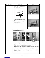
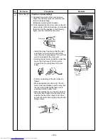
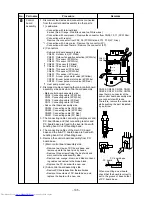
PMV coil
Lead wire
take-out port
ID mark
ID mark
Positioning bracket
at coil side
Positioning concavity
at PMV unit side
(72˚ pitch)
PMV unit
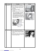
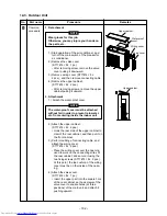
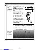
Hooking claw
Minus screwdriver
No.
9
10
Part name
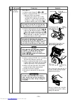
Pulse motor
valve coil
Fan guard
Procedure
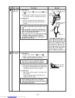
1. Detachment
1) Perform step 1. in
2
, all the steps in
3
and 1.
in
5
.
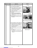
2) Release the coil from the notch by turning it,
and remove coil from the pulse motor valve.
2. Attachment
1) Put the coil deep into the bottom position.
2) Fix the coil firmly by turning it to the notch
position.
The pulse motor valve has A, B and C room
side.
After mounting it, check that coil at B room
side (Nothing is marked on the pulse motor
valve.) is connected to CN702.
Check that coil at C room side (Red marking
is marked on the pulse motor valve.) is
connected to CN703 of the control board
assembly respectively.
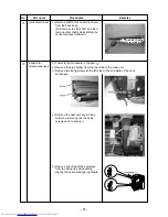
1. Detachment
1) Perform work of item 1 of
1
and 1 of
2
.
2) Remove the front cabinet, and put it down so
that fan guard side directs downward.
Perform work on a corrugated cardboard,
cloth, etc. to prevent flaw to the product.
3) Remove the hooking claws by pushing minus
screwdriver according to the arrow mark in the
right figure, and remove the fan guard.
2. Attachment
1) Insert claw of the fan guard in the hole of the
front cabinet.
Push the hooking claws (12 positions) by
hands and fix the claws.
All the attaching works have completed.
Check that all the hooking claws are fixed to
the specified positions.
Remarks
MountMounting Method of
Pulse Motor Valve (PMV) Coil
Set the positioning bracket on the
PMV coil to a concavity at PMV
unit side and fix PMV coil. In this
time, match color of ID mark at
the coil side with that of ID mark
at the PMV unit side. Make sure
also that pipes do not deform
when inserting and fixing the coil.
Содержание RAS-3M18SACV-E
Страница 21: ... 21 4 2 Outdoor Unit RAS 3M18SAV E RAS 3M18SACV E ...
Страница 110: ... 110 MCC 1438 ...
Страница 111: ... 111 MCC 818 ...


