


– 36 –
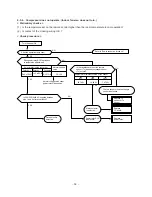
Check
code
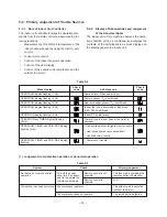
Table 9-5
Condition
Indicated when
detected abnor-
mal.
Indicated when
detected abnor-
mal.
Indicated when
detected abnor-
mal.
Indicated when
detected abnor-
mal.
Indicated when
detected abnor-
mal.
Indicated when
detected abnor-
mal.
Block level
Check
code
Block
Indoor PC
board
Cable
connection/
Thermal fuse
Refrigerant
system
Symptom
Thermo sensor
short/break.
Heat exchanger
sensor short/
break.
Indoor fan lock,
abnormality of
indoor fan.
Abnormality of
other indoor unit
PC board.
• Thermal fuse
cut off.
• Indoor fan lock,
abnormality of
indoor fan.
• Gas shortage.
(gas leak)
• Other refriger-
ant cycle
trouble.
• Heat exchanger
sensor off/
break/short.
• Overload relay
break
Air conditioner
status
Continued
operation
Continued
operation
All off.
Continued
operation
All off.
All off.
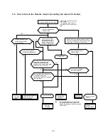
Diagnosis function
Judgement and action
• Check thermo sensor.
• If it is OK, check PC
board. (Around sensor
circuit)
• Check heat exchanger
sensor.
• If it is OK, check PC
board. (Around sensor
circuit)
• Check motor.
• Replace PC board, if
the same failure
occurs, after the motor
check.
Replace PC board.
• Check thermal fuse.
• If it is OK, check
motor.
• If motor is OK, check
PC board. (12V power
circuit)
• Check gas quantity.
(Check gas leakage)
• If it is OK, check heat
exchanger sensor.
• If heat exchanger
sensor is OK, check
overload relay.
• If overload relay is OK,
check refrigerant
cycle.
• If refrigerant cycle is
OK, check PC board.
Содержание RAS-07EAH
Страница 43: ... 43 9 6 PC Board Layout Top view ...
Страница 44: ... 44 Bottom view ...
Страница 48: ...TOSHIBA CORPORATION 1 1 SHIBAURA 1 CHOME MINATO KU TOKYO 105 01 JAPAN ...


