background image


For additional assistance, please contact Toshiba Adjustable Speed Drive Marketing Dept. at (800) 872-2192  
 

Page: 1 of 6 


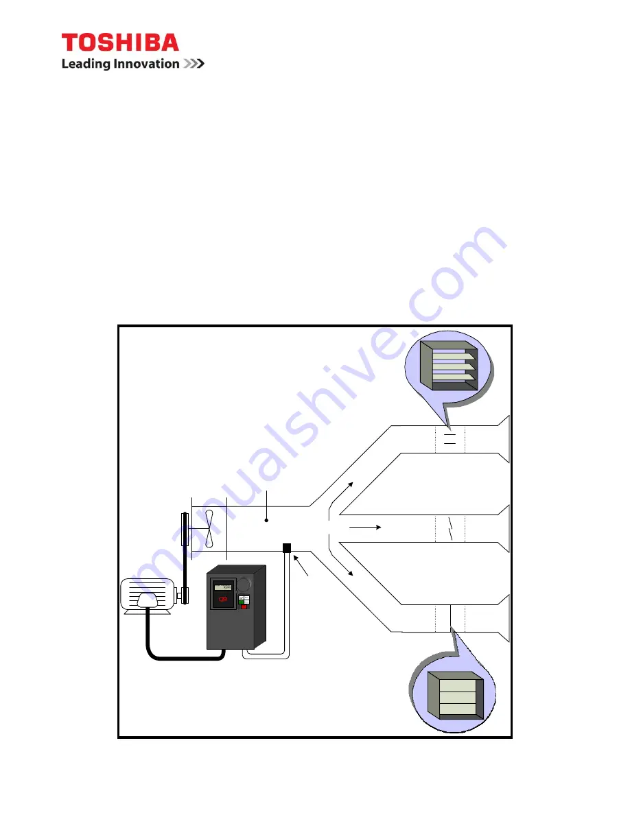
Pressure 

Transducer

Air Flow

Damper

Damper

Damper

Area in which constant 

pressure is desired

4-20 mA Feedback

Q9


APPLICATION GUIDELINE 1.1 

Process PID 

Introduction  

The built-in Process PID control of the Q9 can be used to maintain a constant process variable such 
as flow, pressure, temperature, or level. In the example below, the Q9 is being used to vary the speed 
of the motor/fan to maintain a constant static pressure in the ductwork. As the dampers on the output 
side of the fan are opened, the static pressure in the system will begin to drop. The drive senses this 
change in static pressure via a 4-20mA feedback signal and the drive will increase the speed of the 
motor/fan to bring the static pressure to the desired level. Conversely, the drive will slow the 
motor/fan down as the dampers close to compensate for the increase in pressure. The rate at which 
the drive responds to changes in the feedback signal is adjustable via three parameters (Proportional 
Gain, Integral Time, and Differential Time) and will need to be field-tuned. 


Содержание Q9 HVAC

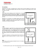
Страница 1: ...peed of the motor fan to maintain a constant static pressure in the ductwork As the dampers on the output side of the fan are opened the static pressure in the system will begin to drop The drive senses this change in static pressure via a 4 20mA feedback signal and the drive will increase the speed of the motor fan to bring the static pressure to the desired level Conversely the drive will slow t...

Страница 2: ...al Because the V I terminal is an isolated analog input and the transducer is powered from P24 the current loop will not be complete A jumper will need to be placed between CC and IICC to make the V I terminal non isolated 4 Wire A 4 wire transducer is powered from an external source and does not use the drive for power Two of the wires will connect to the external power source The feedback signal...

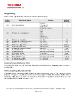
Страница 3: ... 00 2 55 0 00 F367 Process Upper Limit Lower Limit Upper Limit 60 00 Hz F368 Process Lower Limit Lower Limit Upper Limit 0 00 Hz F369 PID Control Wait Time 0 2400 sec 0 sec F370 PID Output Upper Limit Lower Limit Upper Limit 60 00 Hz F371 PID Output Lower Limit Lower Limit Upper Limit 4 00 Hz F372 Process Increasing Rate 0 1 600 0 sec 10 0 sec F373 Process Decreasing Rate 0 1 600 0 sec 10 0 sec En...

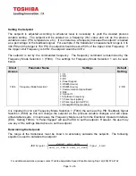
Страница 4: ...quency Mode Selection 1 can be seen below Direct Access Parameter Name Settings Default Setting F004 Frequency Mode Selection 1 1 V I 2 RR 3 RX 4 Panel Keypad 5 RS485 2 wire 6 RS485 4 wire 7 Communication Option Board 8 RX2 9 Option V I 10 Up Down Frequency 11 Pulse Input option 12 Pulse Input motor CPU 13 Binary BCD Input option 2 RR It is important not to set Frequency Mode Selection 1 F004 the ...

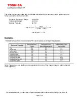
Страница 5: ...te the setpoint on a pressure control system with the following transducer characteristics Pressure Transducer Range 0 300 PSI Transducer Output 4 20 mA Desired Pressure 60 PSI ASD Setpoint Hz PSI PSI PSI 60 0 300 60 ASD Setpoint 12 Hz Examples Note These values are starting point suggestions for tuning They may or may not get the desired result right away ...

Страница 6: ...shiba Adjustable Speed Drive Marketing Dept at 800 872 2192 Page 6 of 6 Revision History Rev Date Written Revised By Approved By Description 1 1 6 23 2011 Joshua Austin Terry Voigt Formatting Revised to incorporate document control requirements ...

Отзывы: