background image

113

Forma

Este manual

M5 × 16L

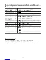
Componentes accesorios y componentes de suministro local

H

 Componentes accesorios

Nombre del componente

Manual de instalación

Tubo de aislamiento térmico

Patrón de instalación

Calibrador de instalación

Tornillo de fijación del
patrón de instalación

Aislante térmico

Arandela

Abrazadera de la manguera

Tubo flexible

Aislante térmico  A

Aislante térmico  B

Cantidad

1

2

1

2

4

1

8

1

1

1

1

Utilización

(Recuerde entregar al cliente)

Para el aislamiento térmico de la sección de conexión de
tubos

Para confirmar la abertura del techo y la posición de la unidad
principal

Para situar la posición en el techo
(se debe utilizar junto con el plano de instalación)

Para fijar el patrón de instalación

Para el aislamiento térmico de la sección de conexión de
drenaje

Para colgar la unidad

Para conectar el tubo de drenaje

Para ajustar la parte exterior del núcleo del tubo de drenaje

Para aislar el orificio de conexión de cables

Para aislar el orificio de conexión de cables

Tubería de refrigerante

• No se puede utilizar el juego de tuberías que se utiliza para el refrigerante convencional.

• Utilice tubos de cobre con un grosor de 0.8 mm o superior para Ø6.4, Ø9.5 y Ø12.7.

• La tuerca abocardada y los trabajos de abocardado difieren de los del sistema de refrigerante convencional.

Utilice la tuerca abocardada que está instalada en la unidad interior del acondicionador de aire.

Содержание MMU-AP0071MH

Страница 1: ...ità interna Unidad interior 4 way Air Discharge Cassette Type Type cassette à 4 voies de soufflage 4 Wege Kassetten Modell Tipo a cassetta per mandata d aria a 4 vie Modelo de cassette con descarga de aire de 4 vías MMU AP0071MH MMU AP0091MH MMU AP0121MH MMU AP0151MH MMU AP0181MH Strictly for commercial use only Uniquement à usage commercial Nur für den gewerblichen Bebrauch Assolutamente solo per...

Страница 2: ...ss Sie sich für dieses Klimagerät entschieden haben In diesem Handbuch wird die Installation der Inneneinheit beschrieben Bevor Sie mit der Installation beginnen lesen Sie dieses Handbuch sorgfältig Wenn Sie zu einem Installationsbetrieb oder zu einem Händler gehören geben Sie das Handbuch an Ihren Kunden weiter und erklären ihm den Inhalt Rohrleitungsverbindungen wieY Abzweige Abzweiganschlüsse u...

Страница 3: ...EHRUNGEN 58 2 AUSWAHL DES AUFSTELLUNGSORTES 59 3 INSTALLATION DER RAUMEINHEIT 61 4 INSTALLATION DES KONDENSWASSER ABLAUFS 65 5 KÜHLMITTELLEITUNGEN 68 6 ELEKTROARBEITEN 70 7 STEUERUNGSMÖGLICHKEITEN 74 8 TESTLAUF 77 9 FEHLERSUCHE 79 10 WARTUNG 84 Accessori e parti da acquistare sul posto 85 1 PRECAUZIONI PER LA SICUREZZA 86 2 SCELTA DEL POSTO D INSTALLAZIONE 87 3 INSTALLAZIONE DELL UNITÀ INTERNA 89 ...

Страница 4: ...al Heat insulating pipe Installation pattern Installation gauge Pattern fixing screw Heat insulator Washer Hose band Flexible hose Heat insulator A Heat insulator B Q ty 1 2 1 2 4 1 8 1 1 1 1 Usage Ensure handover to customer For heat insulation of the pipe connecting section For checking of ceiling opening and the main unit position For positioning of the ceiling position To be used with the inst...

Страница 5: ...problems due to pressure resistances and impurities within the pipe CAUTION To Disconnect the Appliance from Main Power Supply This appliance must be connected to the main power supply by means of a switch with a contact separation of at least 3 mm WARNING Ask an authorized dealer or qualified installation professional to install maintain the air conditioner Inappropriate installation may result i...

Страница 6: ...ust be installed in a location that can support the weight of the unit effectively If the unit is not installed on a foundation that can support its weight effectively the unit may fall down resulting in possible human injury Where required ensure that the units installation is sufficient enough to withstand against an earthquake An insufficient installation could result in the unit falling causin...

Страница 7: ...arately and In case of installation to high ceiling within this Manual Installable ceiling height list Unit m REQUIREMENT When high ceiling 1 or 3 is used with 4 way blowing a draft is easily recognized due to drop of discharge temperature The air filter cleaning signal duration Notification of filter cleaning on the remote controller can be changed according to the condition of installation If th...

Страница 8: ... out the product and then place it on the floor so that the same surface directs underneath as it is placed in the package If the both sides are turned over a deformation of mounting metal of the ceiling panel which is sold separately etc may be caused Accordingly the product may be damaged and the installation becomes impossible in some cases REQUIREMENT Strictly comply to the following rules to ...

Страница 9: ...eiling Bottom face of ceiling Refrigerant pipe Gas 0151 0181MH Ø12 7 0071 to 0121MH Ø9 5 Refrigerant pipe Liquid Ø6 4 268 27 63 134 145 5 220 5 1000 or more 1000 or more Obustacle 1000 or more 15 or more 15 or more Drain up standing up size Note As ABS is used for the drain discharge port of the main unit the vinyl chlor paste cannot be used Use the flexible hose Band fix included in the package S...

Страница 10: ...nstruction and add support for fixing the end of ceiling panel Installation of hanging bolt Use M10 hanging bolts 4 off locally procured When mounting the unit set the pitch of the hanging bolts according to the size of the unit as detailed on the dimensional drawing M5 16L screws Attached These screws are exclusive to the installation pattern When installing the ceiling panel the other exclusive ...

Страница 11: ...etween the fan and the bell mouth Running the unit without removing the cushion may damage the fan motor Indoor unit Level vial Horizontal within 5 mm Hanging bolt Hanging metal Installation gauge Ceiling board 10 to 42 mm 2 23 to 28 mm 1 Installation of ceiling panel Sold separately Install the ceiling panel after completion of the installation of the indoor unit including all piping and wiring I...

Страница 12: ... Pipe material Insulator and size The following materials for piping work and insulation are to be procured locally Trap Arched shape Support bracket 1 100 or more downward Heat insulator 1 5m to 2m NO GOOD As long as possible 10cm VP30 or more Downward slope 1 100 or more VP25 VP25 VP25 Collective pipes Connection of flexible hose Insert the soft socket of the supplied flexible hose into the conn...

Страница 13: ...ump Ensure drainage is checked during cooling mode When the electric work has finished Before installing the ceiling panel pour water as shown in the following figure check water drains from the drain pipe connecting port Transparent in COOL mode and then check there are no water leaks from the drain pipes When the electric work has not finished Pull out the float switch connector 3P Red from P C ...

Страница 14: ...ulation Flexible hose Hose band Attached heat insulator Heat insulator to be procured locally Hard vinyl chloride pipe CAUTION Ensure water is poured slowly To reduce risk of water spreading throughout the unit resulting in a possible fault 4 DRAIN PIPING WORK Water 1500cc to 2000cc Insert the leading part of the hose between the heat exchanger and the drain pan and then bend it downward Check pan...

Страница 15: ...e pipes are not contaminated with dust oil moisture etc Pipe flaring Flaring 1 Cut the pipe with a pipe cutter 2 Place flare nut onto the pipe and flare the pipe Use the flare nut fitted to the unit or one that is R410A compatible As the flaring sizes of R410A differ from that used on R22 It is recommended to use a dedicated R410A flaring tool However a conventional flare tool can be used by adjus...

Страница 16: ...rature of the liquid and the gas pipes are reduced Therefore ensure sufficient insulation is fitted to prevent dew condensation On the gas side ensure that the heat insulation used is heat resistant to a minimum temperature of 120 C Using the supplied heat insulation Insulate the interconnecting parts of the indoor unit ensuring that there is no exposure of any refrigerant pipework As detailed in ...

Страница 17: ...may cause an electric shock or a fire CAUTION Ensure an earth leakage breaker is installed Failure to install may result in a electric shock REQUIREMENT For power supply wiring strictly conform to the Local authorities in each country For wiring of the power supply of the outdoor units follow to the outdoor unit Installation Manual Never connect 220 240V control wiring to the terminal blocks U1 U2...

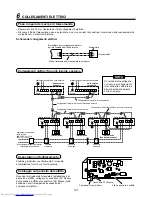
Страница 18: ...oller inter unit wiring Indoor unit Remote controller Indoor unit L1 L2 Ln Max 8 units Indoor unit Indoor unit Remote controller wiring CAUTION The remote controller wire Communication line and AC220 240V Power supply wires cannot be parallel to contact each other and cannot be stored in the same conduits If doing so a trouble may be caused on the control system due to noise etc 6 ELECTRIC WORK In...

Страница 19: ... fitted to the electric parts box Do not apply tension to the connecting section of the terminal block Using the supplied thermal insulation for the sealing of the cable connecting port seal the cable connecting port Otherwise dew condensation may be caused Mount the cover of the electric parts box ensuring the cables are not pinched Mount the cover after the ceiling panel has been wired to the el...

Страница 20: ...per the Installation Manual of the ceiling panel connect the connector 2P Red of the ceiling panel to the connector 5P White onto the P C board within the electric parts box 6 ELECTRIC WORK Connection of shield wire closed terminal Control wiring between indoor and outdoor units Control wiring between outdoor units Outdoor power supply Control wiring between indoor units U2 U1 A B B A Indoor unit ...

Страница 21: ...ure Check that the displayed item code is 10 If the item code indicates any characters other than 10 push the TEST button to erase the display and retry the operation from the first step For some time after the TEST button has been pushed the operation of the remote controller cannot be accepted In a group control the firstly displayed indoor unit No becomes the center unit Each time the UNIT butt...

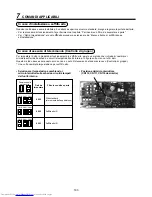
Страница 22: ...peration there is a method that requires the changing of the short plugs on the indoor P C board The details are shown in the below table This method is only to be used where a standard wired remote controller Group control is not used Upon changing the high ceiling setting Select setting by the changing of the short plugs on the indoor P C board Short plug position CN112 CN111 CN110 from the left...

Страница 23: ...ta of the required temperature shift value from the below table Group control In a group control a remote controller can control up to a maximum of 8 units For cabling procedure and cables of the individual line Identical refrigerant line system refer to Electric work in this Manual Wiring between indoor units in a group is performed in the following method Connect the indoor units by connecting t...

Страница 24: ...t operation Before turning on the power supply carry out the following procedures 1 Using 500V megger check there is 1MΩ or more between the terminal block of the power supply and the earth If 1MΩ or less is detected do not run the unit 2 Check that all the valves of the outdoor unit are fully opened WARNING To protect the compressor at startup Ensure the power supply is left on for 12 or more hou...

Страница 25: ...LED flash during test operation Under status of TEST RUN ON the temperature adjustment from the wireless remote controller is invalid Do not use this method in the operation other than test operation because the equipment is damaged Use either COOL or HEAT operation mode for a test operation The outdoor unit does not operate approx 3 minutes after power ON and operation stop After the test operati...

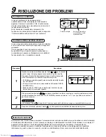
Страница 26: ... FIX TIME MODE VENT UNIT SET CL FILTER RESET TEST TIMER SET Procedure 1 2 3 Description When pushing the SET and TEST buttons simultaneously for 4 seconds or more the display similar to the one shown in the figure to the right will appear If Service Check is displayed the fault code will be stored in the error history mode 01 Order of error history is displayed in CODE No window Check Code is disp...

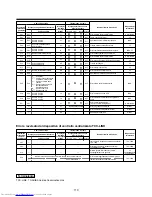
Страница 27: ...nsmission error Remote controller E03 97 l l Communication error between indoor and remote controller Detected at indoor side Indoor E04 04 l l Communication circuit error between indoor outdoor Detected at indoor side Indoor E06 E06 No of indoor units in which sensor has been normally received 04 l l Decrease of No of indoor units I F E07 l l Communication circuit error between indoor outdoor Det...

Страница 28: ...Comp 1 case thermo operation I F H06 H06 20 l l Low pressure protective operation I F H07 H07 d7 l l Oil level down detective protection I F H08 H08 01 TK1 sensor error 02 TK2 sensor error 03 TK3 sensor error 04 TK4 sensor error d4 l l Oil level detective temp sensor error I F H14 H14 44 l l Comp 2 case thermo operation I F H16 H16 01 TK1 oil circuit system error 02 TK2 oil circuit system error 03...

Страница 29: ... P20 22 l ALT High pressure protective operation I F 0 IGBT short 1 Fan motor position detective circuit error 3 Fan motor trouble C TH sensor temp error Heat sink overheat D TH sensor error P22 P22 E Vdc output error 1A l ALT Outdoor fan IPDU error IPDU P26 P26 01 Comp 1 side 02 Comp 2 side 14 l ALT G TR short protection error IPDU P29 P29 01 Comp 1 side 02 Comp 2 side 16 l ALT Comp position dete...

Страница 30: ...isappear However if the error continues after the unit has been stopped the check code will immediately be displayed when the unit is restarted 9 TROUBLESHOOTING Used characters Characteristics of code classification Block display Check code in current system Hexadecimal notation 2 digits Few classification of communication incorrect setup system Indoor P C board Outdoor P C board Cycle Communicat...

Страница 31: ...ount the air outlet flap First push in the one side and insert the opposite side by sagging the center downwards Be careful to insert the flap in the correct direction Insert the flap with the printed mark facing upwards and the arrow on the flap pointing in the outward direction 1 Open the air inlet grille Slide the air inlet grille buttons to detach the air inlet grille from the main ceiling pan...

Страница 32: ...s de fixation du gabarit Isolant thermique Rondelle Collier de serrage du tuyau flexible Tuyau flexible Isolant thermique A Isolant thermique B Quantité 1 2 1 2 4 1 8 1 1 1 1 Emploi N oubliez pas de le remettre au client Pour la gaine de calorifugeage des sections de raccordement des tuyaux Pour vérifier l ouverture du plafond et la position de l unité principale Pour choisir l emplacement au plaf...

Страница 33: ... ne pas provoquer de panne causée par la résistance à la pression et à la présence d impuretés dans les tuyaux ATTENTION Pour déconnecter l appareil du secteur Cet appareil doit être connecté au secteur via un interrupteur ayant une séparation de contact d au moins 3 mm AVERTISSEMENT Demandez à un revendeur autorisé ou à un installateur professionnel d installer le climatiseur d effectuer son entr...

Страница 34: ...être installé dans un endroit en mesure de supporter le poids de l unité Si vous n installez pas l unité sur un support en mesure de supporter son poids elle risque de tomber et de blesser quelqu un Si les règlements le prescrivent vérifiez si l installation des unités est assez solide pour supporter un tremblement de terre Si l installation n est pas assez solide l unité risque de tomber et de bl...

Страница 35: ... d air La minuterie du signal d encrassement du filtre Signalisation du nettoyage du filtre sur la télécommande peut être modifiée en fonction des conditions de l installation Vous pouvez modifier la configuration de la minuterie d alarme du filtre Indiquant de nettoyer le filtre sur la télécommande en fonction de l installation Si la pièce n est pas suffisamment chauffée à cause de l endroit de l...

Страница 36: ...a surface d appui soit la même que celle dans l emballage Si vous le posez à l envers vous risquez de déformer le support métallique du panneau de plafond vendu séparément etc Vous risquez en outre d endommager l appareil ou de ne pas pouvoir l installer 2 SELECTION DU LIEU D INSTALLATION CONDITIONS REQUISES Observez scrupuleusement les règles suivantes pour éviter d endommager les unités intérieu...

Страница 37: ...lafond Tuyau du réfrigérant Gaz 0151 0181MH Ø12 7 0071 à 0121MH Ø9 5 Tuyau du réfrigérant Liquide Ø6 4 268 27 63 134 145 5 220 5 1000 ou davantage 1000 ou davantage Obstacle 1000 ou davantage 15 ou davantage 15 ou davantage Dimension maxi de l évacuation montante REMARQUE Comme l orifice d évacuation de l unité principale est en ABS vous ne pouvez pas utiliser de pâte de chlorure de vinyle Utilise...

Страница 38: ... Comment utiliser le gabarit de montage joint Le gabarit de montage se trouve à l intérieur de l emballage du climatiseur Faux plafond existant Aidez vous du gabarit pour définir la position et la dimension de l ouverture ainsi que l emplacement des boulons de suspension Faux plafond nouveau Aidez vous du gabarit pour définir la position de l ouverture du nouveau plafond Coupez la fente de l unité...

Страница 39: ...ger le moteur du ventilateur Installation du panneau pour plafond vendu séparément Montez le panneau de plafond après avoir achevé l installation de l unité intérieure y compris les travaux de plomberie et d électricité Montez le panneau de plafond de la façon indiquée sur le Manuel d installation Vérifiez si les dimensions de l installation de l unité intérieure et de l ouverture du plafond sont ...

Страница 40: ...0 ou davantage Pente descendante de 1 100 ou davantage VP25 VP25 VP25 Tuyaux collectifs Collier de serrage fourni Flexible fourni Orifice de raccordement du tuyau d évacuation manchon dur Tuyau en chlorure de vinyle dur VP25 à acheter sur place Adhésif interdit Manchon souple Manchon dur Manchon pour VP25 acheté sur place Isolez correctement les tuyaux d évacuation et les raccordements des unités ...

Страница 41: ...ctrique est terminée Avant de monter le panneau de plafond versez de l eau de la façon illustrée sur la figure suivante et vérifiez si l eau est évacuée à travers l orifice du tuyau d évacuation transparent pendant le fonctionnement en mode FROID puis vérifiez s il n y a pas de fuites d eau au niveau des tuyaux d évacuation Lorsque l installation électrique n est pas terminée Sortez le connecteur ...

Страница 42: ...z à verser l eau lentement Pour éviter que l eau ne se répande à travers l unité et ne provoque une panne Flexible Collier de serrage du tuyau flexible Isolant thermique fourni Isolant thermique non fourni Tuyau en chlorure de vinyle dur 4 INSTALLATION DES TUYAUX D EVACUATION Eau 1500 à 2000 cc Placez l extrémité du tuyau flexible entre l échangeur de chaleur et le bac d évacuation puis pliez le v...

Страница 43: ... liquide Tuyau sans raccord désoxydé au phosphore pour climatiseur Type de 0071 à 0121 Type de 0151 à 0181 Ø9 5 Ø12 7 Ø6 4 Ø6 4 Utilisez des tuyaux neufs et propres et veillez à ce qu ils ne soient pas contaminés par de la poussière de l huile de l humidité etc Evasement du tuyau Evasement 1 Coupez le tuyau avec un coupe tube Dimension en mètres du diamètre de l évasement A Unité mm 2 Insérez un é...

Страница 44: ...ge à la section de raccordement des tuyaux de l unité intérieure jusqu à la racine et sans exposer les tuyaux L exposition à l extérieur des tuyaux se soldera par une fuite d eau Impérial de type à papillon Raccordement du tuyau de réfrigérant Raccordez tous les tuyaux de réfrigérant avec des évasements L unité est étanche à la pression atmosphérique Il est donc normal d entendre un chuintement lo...

Страница 45: ...e ou l installation incomplète vous pouvez provoquer une électrocution ou un incendie ATTENTION N oubliez pas de monter un disjoncteur Si vous ne le montez pas vous risquez de provoquer une électrocution CONDITIONS REQUISES Pour les câbles d alimentation respectez scrupuleusement la réglementation locale de chaque pays Pour les câbles d alimentation des unités extérieures suivez le Manuel d instal...

Страница 46: ...il de la télécommande ligne de communication et les fils de 220 240V CA ne doivent pas être parallèles et entrer en contact et ne doivent pas être placés dans les mêmes gaines En cas contraire les bruits etc gênent le fonctionnement du système de commande Câblage de liaison entre la télécommande et les unités Unité intérieure Télécommande Unité intérieure L1 L2 Ln Maxi 8 unités Unité intérieure Un...

Страница 47: ...de serre fils sur le boîtier électrique N exercez aucune pression sur la section de raccordement du bornier Avec l isolant thermique fourni pour sceller l orifice de raccordement des câbles scellez l orifice de raccordement des câbles Autrement des condensats pourraient se former Montez le couvercle du boîtier électrique sans pincer les câbles Montez le couvercle après avoir câblé le panneau de pl...

Страница 48: ... 6 TRAVAUX D ÉLECTRICITÉ Bornier de raccordement de la télécommande de l unité intérieure A B A B Conducteur de la télécommande acheté sur place Bornier Unité de la télécommande Connexion du bornier fermé du câble blindé Câblage de commande entre les unités intérieures et extérieures Câblage de commande entre les unités extérieures Alimentation électrique extérieure Câblage de commande entre les u...

Страница 49: ...le début Si vous attendez trop longtemps après avoir appuyé sur la touche TEST le fonctionnement de la télécommande n est plus accepté Dans une commande de groupe le premier n d unité intérieurequis affichedevientl unitéprincipale L afficheur change selon le modèle d unité intérieure Chaque fois que vous appuyez sur la touché UNIT les n des unités intérieures de la commande de groupe s affichent l...

Страница 50: ...uter les fiches courtes de la carte à circuits imprimés de l unité intérieure Le tableau ci dessous l explique en détail Cette méthode n est utilisée que si le système n utilise pas de télécommande filaire traditionnelle Commande de groupe Après avoir modifié la configuration Haut plafond Sélectionnez en permutant les fiches courtes de la carte à circuits imprimés de l unité intérieure Position de...

Страница 51: ...6 C Commande de groupe Une télécommande peut commander un maximum de 8 unités appartenant à un même groupe Pour la procédure de câblage de chaque ligne ligne de réfrigérant identique consultez le chapitre Câblage électrique de ce Manuel Pour effectuer le câblage entre les unités intérieures d un groupe procédez de la sorte Raccordez les unités intérieures en branchant les câbles de connexion des u...

Страница 52: ...lectromagnétique pour effectuer un essai de marche forcé Cela est très dangereux car le dispositif de protection ne marche pas Mode d exécution d un essai de fonctionnement Pour faire fonctionner le ventilateur d une seule unité intérieure mettez d abord l unité hors tension Court circuitez ensuite CN72 sur la carte à circuits imprimés Mettez ensuite l unité sous tension et démarrez la en mode VEN...

Страница 53: ...ommande est désactivé N utilisez pas cette méthode dans un mode autre que l essai de fonctionnement pour ne pas endommager l appareil Utilisez le mode de fonctionnement COOL FROID ou HEAT CHAUD pour effectuer un essai de fonctionnement L unité extérieure ne fonctionne pas pendant environ 3 minutes après l allumage et l arrêt du fonctionnement A la fin de l essai de fonctionnement arrêtez le climat...

Страница 54: ...et d afficher le fonctionnement Cela permet de connaître l état de fonctionnement Cette fonction d autodiagnostic vous permet de trouver les pannes et leur emplacement sur le système de climatisation comme le montre le tableau ci dessous 3 2 1 ON OFF FAN TEMP SWING FIX TIME MODE VENT UNIT SET CL FILTER RESET TEST TIMER SET Procédure 1 2 3 Description Si vous appuyez en même temps sur les touches S...

Страница 55: ...tion au niveau l unité intérieure Unité intérieure E06 E06 N d unités intérieures où signal du capteur a été reçu normalement 04 l l Diminuer le n d unité intérieures I F E07 l l Panne de communication entre unités intérieure et extérieure Détection au niveau l unité extérieure I F E08 E08 Adresses unité intérieure doublées 96 l l Adresses unité intérieure doublées U intérieure I F E09 99 l l Télé...

Страница 56: ...nctionnement thermo boîtier comp 1 I F H06 H06 20 l l Fonctionnement protection basse pression I F H07 H07 d7 l l Protection détection niveau huile bas I F H08 H08 01 Panne capteur TK1 02 Panne capteur TK2 03 Panne capteur TK3 04 Panne capteur TK4 d4 l l Panne circuit détection niveau huile I F H14 H14 44 l l Fonctionnement thermo boîtier comp 2 I F H16 H16 01 Panne circuit huile TK1 02 Panne circ...

Страница 57: ...nctionnement protection haut pression I F 0 Court circuit transistor bipolaire IGBT 1 Panne du circuit de déection du moteur du ventilateur 3 Panne du moteur du ventilateur C Panne de temp du capteur de tempéature surchauffe du puits de chaleur D Panne du capteur de tempéature P22 P22 E Panne sortie CCV 1A l ALT Panne IPDU ventilateur extérieur IPDU P26 P26 01 Niveau comp 1 02 Niveau comp 2 14 l A...

Страница 58: ...Afficheur A C E F H J L P Classement Non utilisé Pannecommandecentrale Pannedecommunication Panne chaque capteur panne Panne protection compresseur Non utilisé Erreur configuration Autres pannes Fonctionnementdispositifdeprotection Affichage sur télécommande à fil s éclaire UNIT No N UNITÉ Code de vérification lampe témoin fonctionnement verte clignote Affichage sur le capteur de la télécommande s...

Страница 59: ...Poussez d abord un côté puis introduisez l autre côté en pliant le centre vers le bas Faites attention à introduire le volet dans le bon sens Introduisez le volet avec la partie portant le signe dans le haut et la flèche du volet orientée vers l extérieur Type cassette à 4 voies de soufflage 1 Ouvrez la grille d aspiration de l air Faites glisser les boutons de la grille d aspiration de l air pour...

Страница 60: ...timmung der Deckenöffnung gemeinsam mit der Installationsschablone Zum Anbringen der Installationsvorlage Zur Isolierung der Ablaufrohrverbindungen Zum Abhängen der Einheit Anschluss der Ablaufleitung ZurVerbindung der Ablaufleitung Zur Abdichtung der Kabelanschlüsse Zur Abdichtung der Kabelanschlüsse Kühlmittel Leitungssystem Rohrleitungsmaterial für herkömmliches Kühlmittel kann nicht verwendet ...

Страница 61: ...en Anschlüsse einen Mindestabstand von 3 mm haben an die Hauptstromversorgungangeschlossenwerden WARNUNG Zur Installation und Wartung des Klimagerätes wenden Sie sich an einen autorisierten Händler oder einen qualifizierten Installateur Durch eine nicht fachgerechte Installation kann es zu Wasserschäden Stromschlägen oder sogar zu Bränden kommen Ehe Sie irgendwelche Arbeiten an der Elektrik ausfüh...

Страница 62: ... genug ist um das Gewicht des Gerätes aufzunehmen Ist die Unterkonstruktion für die Belastung nicht geeignet kann das Gerät herunterfallen und so Verletzungen verursachen Stellen Sie falls erforderlich sicher dass die Unterkonstruktion auch einem Erdbeben standhält Durch eine unsachgemäße Installation besteht die Gefahr dass das Gerät herunter fällt und Unfälle verursacht Installieren Sie das Gerä...

Страница 63: ...ie unter Änderung der Zeitvorgabe für die Filterwarnleuchte und Verbesserung der Heizleistung in den entsprechenden Beschreibungen dieses Handbuchs Wenn die Höhe der Decke die Standardhöhen für eine 4 Wege Kassette aus der folgenden Tabelle überschreitet kann es vorkommen dass der Raum nicht ausreichend beheizt werden kann Dann ist es erforderlich das Gerät in den Betriebsmodus für hohe Decken zu ...

Страница 64: ...Sie das Paket nehmen Sie das Gerät heraus und stellen es so auf den Boden dass die gleiche Fläche wie im Paket nach unten zeigt Wenn es umgedreht wird können sich hierdurch die Befestigungsteile für die Deckenkassette die als Zubehör erhältlich ist verformen Durch diese Beschädigung ist es dann nicht mehr möglich dass Produkt ordentlich zu installieren 2 AUSWAHL DES AUFSTELLUNGSORTES VORAUSSETZUNG...

Страница 65: ...itig 0151 0181MH Ø12 7 0071 bis 0121MH Ø9 5 Kältemittelleitung flüssigkeits Ø6 4 268 27 63 134 145 5 220 5 1000 oder größer 1000 oder größer Hindernis 1000 oder größer 15 oder größer 15 oder größer Höhe der Ablaufleitung HINWEIS Wenn ABS als Ablaufrohr für das Hauptgerät verwendet wird darf kein PVC Kleber verwendet werden Verwenden sie den beiliegenden flexiblen Schlauch Schellenbefestigung Unter...

Страница 66: ...g des Klimageräts Vorhandene Deckenöffnung Legen Sie mit Hilfe der Installationsschablone die Position und Größe der Deckenöffnung sowie die Positionen der Abhängebolzen fest Neue Deckenöffnung Legen Sie mit der Schablone die Position der neuen Deckenöffnung fest Schneiden Sie den Bereich für die Haupteinheit aus der Installationsschablone Schneiden Sie die Außenseite der Schablone entsprechend de...

Страница 67: ...heit und der Deckenöffnung VORAUSSETZUNGEN Vergewissern Sie sich dass die Deckenkassette mit der Deckenfläche abschließt Ist dies nicht der Fall kann sich hier Kondenswasser sammeln das zu Wasserschäden führen kann Entfernen Sie zuerst die 4 Eckkappen der Kassette und befestigen sie an der Inneneinheit Aufhängebolzen W3 8 oder M10 Mutter W3 8 oder M10 1 M10 Unterlegscheiben werden mitgeliefert all...

Страница 68: ...seits beigestellt Ablaufrohr Anschlussstutzen VP25 PVC Rohr bauseits bereitzustellen Klebstoffe nicht zulässig Weiches Ende Montierte Rohrschelle Montierter flexibler Schlauch Anschlussstück für VP25 bauseits beigestellt Vergewissern Sie sich dass die Kondensatleitung und der Anschluss an die Inneneinheit isoliert sind Die Kondensatleitung muss ein Gefälle von mindestens 1 haben und darf keine Bög...

Страница 69: ... Elektroinstallation Gießen Sie bevor Sie die Deckenkassette installieren Wasser wie abgebildet in die Kondensatwanne starten Sie die Betriebsart COOL Kühlen und prüfen Sie ob das Wasser durch die Leitungen abläuft Prüfen Sie außerdem ob die Ablaufleitung undichte stellen aufweist Wenn die Elektroinstallation noch nicht fertiggestellt ist Ziehen Sie den Schwimmerstecker 3P rot vom Leiterplatten An...

Страница 70: ...sser langsam einfüllen Anderenfalls kann es passieren dass sich das Wasser in der Inneneinheit ausbreitet und dabei Störungen verursacht Flexibler Schlauch Rohrschelle Wärmeisolierung Bauseits bereitzustellende Isolierung PVC Rohr 4 INSTALLATION DES KONDENSWASSER ABLAUFS Wasser 1 5 bis 2 0 Liter Führen Sie den Anfang des Schlauchs zwischen Wärmetauscher und Auffangschale und biegen Sie ihn dann na...

Страница 71: ...essung mm Gasseite Flüssigkeitsseite Phosphorfreie nahtlose Rohre für Klimageräte Typ 0071 bis 0121 Typ 0151 bis 0181 Ø9 5 Ø12 7 Ø6 4 Ø6 4 Verwenden Sie neue saubere Rohre Achten Sie darauf dass die Rohre nicht mit Staub Öl oder Feuchtigkeit usw verschmutzt sind Rohrbördelung Bördeln 1 Trennen Sie das Rohr mit einem Rohrschneider 2 Setzen Sie eine Bördelmutter auf das Rohr und bördeln Sie es damit...

Страница 72: ...emittel R410A R134a etc zugelassene Prüfgeräte Wärmeisolierung Versehen Sie die gasseitigen und flüssigkeitsseitigen Rohrleitungen jeweils mit einer Wärmeisolierung Im Kühlbetrieb sind die Temperaturen der flüssigkeits und gasseitigen Rohrleitungen niedriger Achten Sie daher darauf dass sie ausreichend isoliert sind um die Bildung von Kondenswasser zu verhindern Auf der Gasseite muss die Isolierun...

Страница 73: ...ße Installation kann zu einem Stromschlag oder zu einem Brand führen VORSICHT Installieren Sie eine Erdschluss Sicherung Beachten Sie dies nicht kann ein Stromschlag die Folge sein VORAUSSETZUNGEN Achten Sie bei der Verlegung der Stromversorgung auf nationale Vorschriften Beachten Sie beim Anschluss der Außeneinheit die Anweisungen des Installationshandbuchs Schließen Sie niemals die Kabel der Str...

Страница 74: ...nbedienung Kommunikation unddieKabelder Stromversorgung Wechselstrom 220 240 V müssen im Abstand zueinander verlegt werden und dürfen nicht durch die gleichenKabelkanälegezogenwerden Beachten Sie dies nicht kann es aufgrund elektrischerStörungenzuFehlfunktionen usw kommen Fernbedienungsverkabelung zwischen den Geräten Raumeinheit Fernbedienung Raumeinheit L1 L2 Ln Max 8 Geräte Raumeinheit Raumeinh...

Страница 75: ...der Kabelklemme Achten Sie darauf dass kein Zug auf die Klemmenleiste wirkt Dichten Sie die Kabeldurchführung mit dem beiliegenden Isoliermaterial ab Ohne Isolierung kann es zur Bildung von Kondenswasser kommen Montieren Sie den Deckel des Schaltkastens ohne dabei die Kabel einzuklemmen Montieren Sie den Deckel erst wenn auch die Deckenkassette mit dem Schaltkasten verdrahtet ist Leiterplatte Deck...

Страница 76: ...EKTROARBEITEN Klemmenleiste für das Fernbedienungskabel der Inneneinheit A B A B Kabel der Fernbedienung bauseits beigestellt Klemmenleiste Fernbedienung Anschlussklemme für Kabelabschirmung Steuerungsverkabelung zwischen Innen und Außeneinheiten Steuerungsverkabelung zwischen Außeneinheiten Stromversorgung Außeneinheit Steuerungsverkabelung zwischen Inneneinheit U2 U1 A B B A Inneneinheit Masse F...

Страница 77: ...ere Zahl als 10 angezeigt drücken Sie TEST um die Anzeige zu löschen und beginnen Sie noch einmal mit dem ersten Schritt Eine Betätigung der Fernbedienung ist für eine kurze Zeit nachdem TEST gedrückt wurde nicht möglich Bei einer Gruppensteuerung wird die erste angezeigte Inneneinheit Nummer zur Zentraleinheit Die Anzeige wechselt je nach Modell der Inneneinheit Jedes Mal wenn Sie UNIT drücken sc...

Страница 78: ...g einer Brücke auf der Leiterplatte der Inneneinheit geändert Details hierzu finden Sie in der nachfolgenden Tabelle Verwenden Sie diese Methode nur wenn keine Kabelfernbedienung Gruppensteuerung vorhanden ist Ändern der Einbauhöheneinstellung Wählen Sie dir Einstellung durch das Umstecken der Brücke auf der Leiterplatte der Inneneinheit Setzen Sie die Jumper CN112 CN111 CN110 von links nach recht...

Страница 79: ... Auslieferung 5000H 10000H Einstelldaten 0000 0001 0002 0003 0004 0005 0006 Temperatur Schaltwert Keine Verschiebung 1 C 2 C bei Auslieferung 3 C 4 C 5 C 6 C Die Zeitvorgabe für die Filterwarnleuchte kann den jeweiligen Installationsbedingungen angepasst werden Folgen Sie den Vorgehensweisen 1 2 3 4 5 6 Für den Code in Vorgehensweise 3 geben Sie 01 ein Zum Einrichten der Daten Set data in Vorgehen...

Страница 80: ... schalten wenn der Raumtemperaturfühler abgeschaltet ist Der Testbetrieb wird um das Gerät zu schonen automatisch nach 60 Minuten abgebrochen Das Gerät wechselt dann zurück in den normalen Betriebsmodus Vorgehensweise 1 2 3 4 5 Beschreibung Halten Sie die Taste TEST für mindestens 4 Sekunden gedrückt TEST wird angezeigt und der gewünschte Testmodus kann ausgewählt werden Drücken Sie die Taste ON O...

Страница 81: ...cht über die Infrarot Fernbedienung geregelt werden Verwenden Sie den Testlauf nicht für den normalen Betrieb da hierdurch das Gerät beschädigt wird Wählen Sie für den Test sowohl den COOL Kühl als auch den HEAT Heiz Modus Die Außeneinheit arbeitet nach dem Einschalten und bei einem Neustart die ersten 3 Minuten nicht Nach Ende des Testlaufs schalten Sie das Klimagerät über die Fernbedienung aus u...

Страница 82: ...ichkeit die jeweilige Funktion zu überprüfen Mit Hilfe der Selbstdiagnose können Probleme oder ein Gerätefehler anhand der nachfolgenden Tabelle leicht gefunden werden 3 2 1 ON OFF FAN TEMP SWING FIX TIME MODE VENT UNIT SET CL FILTER RESET TEST TIMER SET Vorgehensweise 1 2 3 Beschreibung Wenn Sie SET und TEST für mindestens 4 Sekunden gleichzeitig drücken erscheint eine Anzeige die der rechts darg...

Страница 83: ...r IPDU Fehler 06 IPDU2 Lüfter IPDU Fehler 07 Fehler alle IPDUs AI NET Fernbedienungsanzeige 97 04 04 96 99 CF 42 42 89 97 99 96 42 15 15 15 d2 CF Infrarot Fernbedienung Sensorblockanzeige an Empfänger Funktion Uhr Bereit Blinken l l l l l l l l l l l l l l l l l l l l l l l l l l l l l l l l l l l l l l l l Fehlercode Bezeichnung Kommunikationsfehler zwischen Raumgerät und Fernbedienung erkannt du...

Страница 84: ...umgerät TA Sensorfehler TS1 Sensorfehler TH Sensorfehler Versagen des Außentemperatursensors TE TL Versagen des Außendrucksensors TE TL Ps Sensorfehler Pd Sensorfehler Raumgerät anderer Fehler Raumgerät EEPROM Fehler Kompressor Ausfall Fehler Magnetschalter Überspannungsrelais geschaltet Verdichterproblem gesperrt Systemfehler Stromaufnahme Comp 1 Thermo Funktion Überdruckentlastung Ölfilmschutz Ö...

Страница 85: ...keitserkennung Außeneinheit Gasleck Erkennung Zufuhrtemperatur TD2 Fehler 4 Wege Ventil Fehler Überdruck Schutzfunktion IPDU Fehler Außeneinheits Lüfter Fehler Kurzschlusssicherung G TR Systemfehler Comp Position Anderer Fehler an Raumeinheit Gruppenfehler Fehler in Raumgerätegruppe AI NET Kommunikationsfehler Doppelter Netzwerkadapter Anzeigendes Gerät Raumgerät I F IPDU I F IPDU I F Raumgerät Ra...

Страница 86: ...z usw Anzeige A C E F H J L P Klassifizierung Unbenutzt Fehler zentrales Steuersystem Kommunikationsfehler Jeder Sensorfehler Fehlfunktion Verdichterschutzfehler Unbenutzt Einrichtfehler andere Fehler Schutzfunktion Anzeige bei verdrahteter Fernbedienung schaltet ein UNIT No GERÄTE No Prüfcode Betriebsanzeige grün blinkt Anzeige am Sensor bei Infrarot Fernbedienung Die Blockanzeige zeigt eine Komb...

Страница 87: ...Seite und setzen Sie dann die gegenüberliegende Seite ein indem Sie gegen die Mitte drücken Achten Sie auf die Richtung der Lamelle wenn Sie sie wieder einsetzen Die Lamellen müssen so eingesetzt sein dass die Markierung nach oben und der Pfeil nach außen zeigen Ansauggitter Halter Sicherheitsaufhängung Luftfilter Drücken Ansauggitter Halter 1 Einsatz 2 Setzen Sie die Klappen ein indem Sie die Mit...

Страница 88: ... e dell apertura a soffitto Per posizionare la posizione a soffitto da usare insieme alla sagoma per l installazione Per fissare la sagoma per l installazione Per isolamento per riscaldamento della sezione di connessione del tubo di scarico Perappenderel unità Per la connessione del tubo di scarico Per regolare il nucleo esposto del tubo di scarico Per sigillare la porta di connessione fili Per si...

Страница 89: ...are tubazioni di installazioni precedenti sarebbero causa di problemi dovuti ad aumento della presssione e alla presenza d impurità nelle tubature AVVERTENZA Per scollegare l apparecchio dall alimentazione di rete Questo apparecchio deve essere collegato alla rete elettrica per mezzo di un interruttore con una separazione dei contatti di almeno 3 mm TTENZIONE Per installare riparare il condizionat...

Страница 90: ...o addensarsi attorno all apparecchio sarebbe causa di rischio d incendio 2 SCELTA DEL POSTO D INSTALLAZIONE TTENZIONE Installare il condizionatore d aria dove il peso dell apparecchio possa essere sostenuto bene Se il sostegno non è sufficientemente forte l apparecchio potrebbe non solo cadere quanto anche essere causa d infortuni Dove necessario assicurarsi che le unità siano installate in modo d...

Страница 91: ...azione Unità m REQUISITI In caso di altezza soffitto 1 o 3 con sistema di soffio a 4 vie è facile avvertire una corrente d aria dovuta all abbassamento della temperatura dell aria di mandata A seconda delle condizioni di installazione è possibile modificare il tempo di accensione sul telecomando del simbolo del filtro avviso per la pulizia del filtro A seconda delle condizioni di installazione è p...

Страница 92: ...o che la stessa superficie sia rivolta verso il basso come si trovava nell imballaggio Se i due lati fossero capovolti si correrebbero rischi di deformazione del metallo di installazione del pannello del soffitto Conseguentemente il prodotto potrebbe danneggiarsi e l installazione non sarebbe possibile 2 SCELTA DEL POSTO D INSTALLAZIONE REQUISITI Osservare scrupolosamente le seguenti indicazioni p...

Страница 93: ...ratura quadrata per condotto di diramazione Ø150 Facciata inferiore del soffitto Facciata inferiore del soffitto Tubo del refrigerante Gas 0151 0181MH Ø12 7 Da 0071 a 0121MH Ø9 5 Tubo del refrigerante Liquido Ø 6 4 268 27 63 134 145 5 220 5 1000 o più 1000 o più Ostacolo 1000 o più 15 o più 15 o più Formato supporto con scarico in su NOTA Siccome ABS è usato per la presa di mandata dello scarico d...

Страница 94: ...tagliata della struttura del soffitto e aggiungere un sostegno per fissare l estremità del pannello a soffitto Installazione del bullone di sospensione Usare bulloni di sospensione M10 4 unità da acquistare sul posto Per il fissaggio dell unità stabilire il passo dei bulloni di sospensione in funzione della grandezza dell unità con riferimento al disegno con dimensioni Viti M5 16L Fornite in dotaz...

Страница 95: ... con la superficie del soffitto o l unità interna Se il pannello e l unità non combaciano perfettamente potrebbe formarsi condensa a sua volta causa di gocciolamento Per primo rimuovere i 4 cappucci angolari dal pannello a soffitto e poi installare il pannello sull unità interna Bullone di sospensione W3 8 o M10 Dado W3 8 o M10 1 A parte la rondella M10 fornita in dotazione le altre cose devono es...

Страница 96: ...TTO Presa per tubo VP25 in cloruro di polivinile Da acquistare sul posto Allineare la fascetta fornita per il blocco del tubo flessibile di scarico all estremità del tubo flessibile sistemare la parte da avvitare rivolta verso l alto e poi avvitare Corpo unità interna Attacco di connessione del tubo di scarico Trasparente Tubo flessibile Accessorio Tubo VP25 in cloruro di polivinile Da acquistare ...

Страница 97: ...rici sono stati completati Prima d installare il pannello a soffitto versare dell acqua come mostrato nella figura sotto controllare che l acqua sia scaricata dall attacco di connessione per il tubo di scarico trasparente in modalità COOL RAFFREDDAMENTO e verificare che non ci siano perdite dal tubo di scarico Se i collegamenti elettrici non sono stati completati Estrarre il connettore del comando...

Страница 98: ...mente Per ridurre i rischi di spargimento d acqua nell unità che sarebbero causa di guasto Tubo flessibile Fascetta di blocco tubo flessibile Isolante per riscaldamento fornito in dotazione Isolante per riscaldamento da acquistare sul posto Tubo rigido in cloruro di polivinile Acqua da 1500 cc a 2000 cc Inserire la parte di testa del tubo flessibile tra lo scambiatore di calore e la vaschetta di s...

Страница 99: ...oro per condizionatori d aria Tipi da 0071 a 0121 Tipi da 0151 a 0181 Ø9 5 Ø12 7 Ø6 4 Ø6 4 Usare un tubo nuovo e pulito e controllare che nei tubi non ci siano depositi d impurità quali polvere olio muffa ecc Svasatura tubi Svasatura 1 Tagliare il tubo usando un utensile da taglio per tubi 2 Inserire un dado svasato sul tubo e svasare il tubo Utilizzare il dado svasato adatto all unità o un dado c...

Страница 100: ...ne di connessione dei tubi dell unità interna fino all origine senza lasciare tubo esposto L esposizione all esterno di parte di tubo sarebbe causa di perdite d acqua Imperial Tipo con dado ad alette Connessione del tubo del refrigerante Collegare tutti i tubi del refrigerante eseguendo lavori di connessione a svasatura Siccome l unità è a tenuta a pressione atmosferica Non è un anomalia non senti...

Страница 101: ...cosse elettriche o incendi AVVERTENZA Bisogna installare un interruttore per dispersioni a terra Non farlo può essere causa di scosse elettriche REQUISITI Per il collegamento di connessione alla rete d alimentazione elettrica osservare scrupolosamente le direttive della normativa in vigore nel paese Per il collegamento di connessione alla rete d alimentazione elettrica delle unità esterne fare rif...

Страница 102: ...tori non polarizzati Collegamenti elettrici di telecomando e di telecomando inter unità Filo ritorto da 0 5 a 2 0 mm 2 Lunghezza totale dei fili di collegamento del telecomando e di collegamento inter unità per il telecomando L L1 L2 Ln In coso di telecomando solo via cavo In caso di telecomando anche via radio Lunghezza totale dei fili di collegamento inter unità per il telecomando L L1 L2 Ln Fin...

Страница 103: ...la parte di connessione della morsettiera Usando l isolante termico fornito in dotazione per sigillare la porta di collegamento cavi sigillare la porta di collegamento cavi Altrimenti potrebbe formarsi condensa Montare il coperchio della cassetta dei componenti elettrici senza schiacciare i cavi Montare il coperchio dopo che il pannello a soffitto è stato collegato elettricamente alla cassetta dei...

Страница 104: ...a automaticamente unità principale Morsettiera per i collegamenti elettrici del telecomando dell unità interna A B A B Filo del telecomando Da acquistare sul posto Morsettiera Telecomando Connessione di terminale chiuso per cavo schermato Collegamenti elettrici fra le unità interna ed esterna Collegamenti elettrici fra le unità esterna Alimentazione elettrica unità esterna Collegamenti elettrici f...

Страница 105: ...premere il tasto TEST per cancellare il display e poi ripetere l operazione a partire dal primo punto Per un certo tempo dopo la pressione del tasto TEST non vengono accettati i comandi inviati dal telecomando Nel caso di controllo di gruppo l unità interna il cui numero viene visualizzato per primo diventa l unità principale Il display cambia a seconda del modello dell unità interna A ogni pressi...

Страница 106: ... un metodo che richiede di cambiare i microinterruttori della scheda a circuiti stampati dell unità interna In figura sotto ci sono tutti i dati Questo metodo deve essere usato solo se non è usato il telecomando standard via cavo Controllo di gruppo Una volta cambiata impostazione per soffitto alto Selezionare l impostazione cambiando i microinterruttori sulla scheda a circuiti stampati dell unità...

Страница 107: ...erativa di base 1 2 3 4 5 6 Per il codice di voce del passo 3 specificare 06 Per i i dati d impostazione di cui al punto 4 della procedura selezionare i dati di impostazione del valore da cambiare per la temperatura richiesta traendoli dalla tabella riportata qui sotto Dati da impostare 0000 0001 0002 0003 0004 0005 0006 Valore cambio rilevazione temp Nessuna variazione 1 C 2 C Nel momento della s...

Страница 108: ...il funzionamento s interrompe per Thermo OFF della temperatura d ambiente è possibile eseguire un funzionamento di prova forzato seguendo la procedura seguente Per evitare un funzionamento di prova continuato il funzionamento termina automaticamente dopo 60 minuti L unità ripristina la modalità di funzionamento di prima Procedura 1 2 3 4 5 Descrizione Mantenere il tasto TEST premuto per 4 secondi ...

Страница 109: ... Non utilizzare questo metodo se non durante il funzionamento di prova altrimenti si potrebbe danneggiare l apparecchio Per il funzionamento di prova utilizzare la modalità COOL RAFFREDDAMENTO o la modalità HEAT RISCALDAMENTO Dopo l accensione e dopo l arresto del funzionamento l unità esterna non funziona per circa 3 minuti Dopo il termine del funzionamento di prova arrestare il condizionatore d ...

Страница 110: ...asistica di errori in memoria vengono memorizzati fino a 4 guasti occorsi in precedenza La casistica può essere confermata sia in modalità di funzionamento che in modalità di arresto Codice di controllo No d unità interna dove si è verificato un errore di funzionamento CODENo UNIT No R C No Procedura 1 2 3 Descrizione Quando si premono simultaneamente i tasti SET e TEST per 4 secondi o più a lungo...

Страница 111: ...rrore IPDU1 02 Errore IPDU2 03 Errore IPDU1 2 02 Errore IPDU ventola 05 Errore IPDU1 IPDU ventola 05 Errore IPDU2 IPDU ventola 05 Errore IPDU totale Display di comando centralizzato AI NET 97 04 04 96 99 CF 42 42 89 97 99 96 42 15 15 15 d2 CF Nome del codice di controllo Errore di comunicazioni tra il telecomando e l unità interna Rilevato dal telecomando Errore di trasmissione del telecomando Err...

Страница 112: ...TO Errore sensore TA unità interna Errore sensore TS1 Errore sensore TH Errore di cablaggio sensore temp unità esterna TE TL Errore di cablaggio sensore temp unità esterna Pd Ps Errore sensore Ps Errore sensore Pd Errore diverso unità interna Errore EEPROM unità interna Guasto compressore Guasto interruttore elettromagnetico Funzionamento relé di sovracorrente Guasto al compressore blocco Errore s...

Страница 113: ...erdita gas Errore temp scarico TD2 Errore inversione valvola a 4 vie Operazione di protezione alta pressione Errore IPDU ventola unità esterna Errore protezione corto G TR Errore sistema circuito rilevazione posizione comp Errore unità interna diverso Errore unità terminale gruppo Errore in gruppo unità interne Errore sistema comunicazioni AI NET Adattatori rete duplicati Dispositivo di valutazion...

Страница 114: ...nde UNIT No No UNITÀ Codice controllo Spia funzionamento verde lampeggiante Display su parte sensore di telecomando via radio Sul display appare una combinazione di simboli Display a 7 segmenti in unità esterna Vengono visualizzati No unità e codice di controllo In a caso di errore vengono visualizzati alternativamente codice ausiliare codice di controllo e codice secondario Display A C E F H J L ...

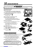
Страница 115: ...nstallare il filtro dell aria 5 Chiudere la griglia d ingresso dell aria Chiudere la griglia d ingresso dell aria e fa scorrereper alloggiare saldamente nel pannello a soffitto 6 Premere il tasto FILTER RESET Il display scompare Pulire il deflettore dell uscita dell aria Se necessario è possibile rimuovere il deflettore dell uscita dell aria per pulirlo 1 Rimuovere il deflettore dell uscita dell a...

Страница 116: ...situar la posición en el techo se debe utilizar junto con el plano de instalación Para fijar el patrón de instalación Para el aislamiento térmico de la sección de conexión de drenaje Para colgar la unidad Para conectar el tubo de drenaje Para ajustar la parte exterior del núcleo del tubo de drenaje Para aislar el orificio de conexión de cables Para aislar el orificio de conexión de cables Tubería ...

Страница 117: ...sistencia a la presión e impurezas dentro del tubo PRECAUCIÓN Para desconectar el aparato de la red eléctrica Este aparato deberá conectarse a la red eléctrica mediante un interruptor con una separación de contacto de como mínimo 3 mm ADVERTENCIA Solicite a un concesionario autorizado o a un instalador profesional cualificado que instale y o realice el mantenimiento del aparato de aire acondiciona...

Страница 118: ...ra alrededor de la unidad podría producirse un incendio 2 SELECCIÓN DEL LUGAR DE INSTALACIÓN ADVERTENCIA Instale el acondicionador de aire en un sitio que aguante sin problemas el peso de la unidad Si no instala la unidad sobre una base que soporte el peso puede caerse y provocar lesiones En los casos en los que sea necesario verifique la instalación de las unidades soporte un posible terremoto Si...

Страница 119: ...ajada en la temperatura de descarga Es posible modificar la duración del indicador de limpieza del filtro de aire Notificación de la limpieza del filtro del control remoto según las condiciones de la instalación La configuración del momento de encendido de la señal de filtro notificación de necesidad de limpiar el filtro del mando a distancia se puede modificar según las condiciones de instalación...

Страница 120: ...ma superficie que dentro del embalaje Si ambos lados están invertidos puede provocar la deformación del metal de instalación del panel del techo que se vende aparte etc El producto también puede resultar dañado y es imposible hacer la instalación en algunos casos 2 SELECCIÓN DEL LUGAR DE INSTALACIÓN REQUISITOS Cumpla estrictamente las reglas siguientes para evitar daños en la unidad interior así c...

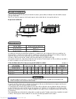
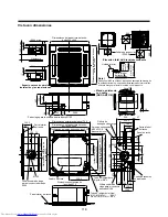
Страница 121: ...arte inferior del techo Parte inferior del techo Tubo de refrigerante Gas 0151 0181MH Ø12 7 De 0071 al 0121MH Ø9 5 Tubo de refrigerante Líquido Ø6 4 268 27 63 134 145 5 220 5 1000 o más 1000 o más Obstáculo 1000 o más 15 o más 15 o más Elevación total del drenaje ascendente Nota Dado que el ABS se utiliza en el puerto de descarga de drenaje de la unidad principal no se puede utilizar pasta de clor...

Страница 122: ...erior del plano según el tamaño de la abertura del techo Hay una ranura en la sección del tamaño estándar de la abertura Instale la unidad interior después de colocar los pernos de suspensión Mediante el plano incluido colóquelos a la unidad interior con los tornillos de fijación provistos M5 16L 4 Plano de fijación a las ménsulas colgantes del panel del techo de la unidad interior Al crear la abe...

Страница 123: ...dad interior Si el panel y la unidad no se corresponden puede formarse condensación que puede provocar una fuga de agua Primero quite las 4 tapas de ángulos del panel del techo y fíjelas a la unidad interior Perno de suspensión W3 8 o M10 Tuerca W3 8 o M10 1 La arandela M10 está incluida todos los demás materiales deben obtenerse localmente 2 Para garantizar que la unidad esté bien instalada el pe...

Страница 124: ...haber daños o fugas de agua en el orificio de conexión del tubo de drenaje Sifón Forma arqueada 1 100 o más hacia abajo Aislante térmico Abrazadera de soporte De 1 5 m a 2 m INADECUADO Lo más largo posible 10 cm VP30 o superior Inclinación hacia abajo de 1 100 o superior VP25 VP25 VP25 Canalización colectora Abrazadera de la manguera incluida Manguera flexible incluida Orificio de conexión del tub...

Страница 125: ...ompletado la instalación eléctrica Antes de instalar el panel del techo vierta agua del modo indicado en la ilustración siguiente Compruebe que el agua se drene desde el orificio de conexión del tubo de drenaje transparente en el modo refrigeración COOL y a continuación compruebe que no haya fugas de agua en los tubos de drenaje Si aún no se ha completado la instalación eléctrica Saque el conector...

Страница 126: ...ir el riesgo de que el agua de distribuya por toda la unidad y pueda ocasionar una falla Manguera flexible Abrazadera de la manguera Aislante térmico incluido con el producto Aislante térmico de suministro local Tubo rígido de cloruro vinílico 4 CANALIZACIÓN DE DRENAJE 1N Agua entre 1500 y 2000 cc Introduzca la parte delantera de la manguera entre el intercambiador de calor y la bandeja de drenaje...

Страница 127: ...l gas mm Ladodellíquido Tubo para aire acondicionado sin juntas de desoxidación de fósforo Typo de 0071 a 0121 Typo de 0151 a 0181 Ø9 5 Ø12 7 Ø6 4 Ø6 4 Utilice tubos nuevos y limpios verifique que no tengan polvo aceite humedad etc Abocardado del tubo Abocinado 1 Corte el tubo con un cortatubos 2 Coloque la tuerca abocardada en el tubo y abocine el tubo Utilice la tuerca abocardada conectada a la ...

Страница 128: ...ra que no se vea el tubo Si el tubo queda expuesto al exterior se originarán fugas de agua Imperial tipo tuerca de mariposa Conexión del tubo de refrigerante Conecte todos los tubos de refrigerante mediante el método de conexión abocardado La unidad está sellada a presión atmosférica No es anormal que no se oiga sonido de Presión al quitar la tuerca abocardada Utilice dos llaves para conectar la t...

Страница 129: ...eléctrica o un incendio PRECAUCIÓN Asegúrese de que el interruptor de fuga a tierra esté instalado De lo contrario podría producirse una descarga eléctrica REQUISITOS Para el cableado de alimentación eléctrica cumpla estrictamente con lo dispuesto por las autoridades de cada país Para el cableado de alimentación eléctrica de las unidades exteriores siga las indicaciones del Manual de instalación d...

Страница 130: ... mando a distancia línea de comunicación y los cables de CA de 220 240V no pueden correr paralelos y entrar en contacto directo y no se pueden colocar en un mismo conducto para cables De lo contrario puede haber problemas en el sistema de control a causa del ruido etc Cableado entre unidades del mando a distancia Unidad interior Mando a distancia Unidad interior L1 L2 Ln máx 8 unidades Unidad inte...

Страница 131: ... componentes eléctricos No aplique tensiones a la sección de conexión del bloque de terminales Utilice el aislante térmico provisto para sellar el orificio de conexión del cableado De lo contrario puede generarse condensación Coloque la tapa de la caja de componentes eléctricos sin enganchar los cables Coloque la tapa después de haber hecho el cableado del panel del techo a la caja eléctrica Placa...

Страница 132: ... 6 INSTALACIÓN ELÉCTRICA Bloque de terminales del cableado del control remoto de la unidad interior A B A B Cable del mando a distancia suministrado en la obra Bloque de terminales Unidad de control remoto Conexión del terminal cerrado de cable blindado Cableado de control entre las unidades interior y exterior Cableado de control entre las unidadad exterior Fuente de alimentación externa Cableado...

Страница 133: ... borrar los elementos de la configuración que ya se hayan ajustado En este caso vuelva al paso 2 del procedimiento Una vez haya finalizado la configuración pulse el botón TEST La configuración se guarda Pulse el botón TEST para eliminar los indicadores y volver al estado de parada normal Tras pulsar el botón TEST y durante un rato el control remoto no admite ninguna orden CODENo UNIT No R C No COD...

Страница 134: ...nidad para funcionamiento con techo alto hay un método que exige cambiar los puentes de la placa de circuitos impresos interior En la tabla siguiente se muestran los detalles Se debe usar este método únicamente si no se utiliza un control remoto estándar con cable Control grupal Al cambiar el ajuste del techo alto Selección del ajuste mediante cambio de los puentes de la placa de circuito impreso ...

Страница 135: ...lor de cambio de temperatura necesario de la tabla siguiente Control grupal En un control grupal un solo control remoto puede controlar un máximo de 8 unidades Para más información acerca del procedimiento de cableado y los cables del sistema de línea individual línea de refrigerante idéntica consulte el apartado Cableado eléctrico de este manual El cableado entre unidades interiores de un mismo g...

Страница 136: ...mbiente desactivado Para evitar que la prueba de funcionamiento siga en marcha de continuo se detiene la operación tras un período de 60 minutos La unidad luego vuelve al funcionamiento original ADVERTENCIA Para proteger el compresor en la puesta en marcha Controle que se mantenga la alimentación durante 12 horas o más antes de la operación Paso 1 2 3 4 5 Descripción Mantenga pulsado el botón TEST...

Страница 137: ...ámbrico se desactiva Utilice este método únicamente para realizar activaciones de prueba ya que de lo contrario puede dañar el equipo Utilice los modos de funcionamiento COOL refrigeración o HEAT calefacción para realizar la activación de prueba La unidad de exterior no opera durante unos 3 minutos después del encendido y la parada de funcionamiento Una vez finalizada la activación de prueba deten...

Страница 138: ...erfaz exterior En consecuencia es posible conocer el estado de funcionamiento de la unidad Mediante esta función de autodiagnóstico es posible encontrar un problema y la ubicación del error del sistema de aire acondicionado del modo indicado en la tabla siguiente 3 2 1 ON OFF FAN TEMP SWING FIX TIME MODE VENT UNIT SET CL FILTER RESET TEST TIMER SET Paso 1 2 3 Descripción Al pulsar los botones SET ...

Страница 139: ...rror en IPDU1 02 Error en IPDU2 03 Errores en IPDU1 y 2 04 Error en IPDU del ventilador 05 Error en IPDU1 IPDU del ventilador 06 Error en IPDU2 IPDU del ventilador 07 Error en todas las IPDU Pantalla de indicadores del control central AI NET 97 04 04 96 99 CF 42 42 89 97 99 96 42 15 15 15 d2 CF Mando a distancia inalámbrico Pantalla de indicadores del bloque sensor de la unidad de recepción Funcio...

Страница 140: ...sor TL Error del sensor TO Error del sensor TA interior Error del sensor TS1 Error del sensor TH Problema de cableado en el sensor de temperatura exterior TE TL Problema de cableado en el sensor de presión exterior Pd Ps Error del sensor Ps Error del sensor Pd Error en otro componente interior Error de la EEPROM interior Avería del compresor Error en el interruptor de magneto Activación del relé d...

Страница 141: ...entilador interior Error de detección de retorno de líquido exterior Detección de escape de gas Error en TD2 de temperatura de descarga Error de inversión de la válvula de 4 vías Funcionamiento de protección de alta presión Error de IPDU del ventilador exterior Error de protección de cortocircuito G TR Error del sistema del circuito de detección de posición del compresor Otro error de la unidad in...

Страница 142: ...ema de comunicación Error avería de todos los sensores Error del sistema de protección del compresor No se utiliza Error de configuración otros errores Funcionamiento del dispositivo de protección Indicaciones en el mando a distancia con cable se enciende UNIT No parpadean el número de unidad el código de verificación y la luz de funcionamiento verde Indicaciones en el elemento sensor del control ...

Страница 143: ...urante un período suficiente de tiempo en un lugar a la sombra 4 Monte el filtro de aire 5 Cierre la rejilla de entrada de aire Cierre la rejilla de entrada del aire deslice el botón para ubicarlo en el panel del techo y fijarlo bien 6 Pulse FILTER RESET Desaparece el mensaje Limpieza de la aleta de salida de aire Es posible quitar aleta de salida de aire para limpiarla cuando sea necesario Rejill...

Страница 144: ...through leakage of R 410A is minimal However with the recent increase in the number of high density buildings and use of multi air conditioner systems to ensure effective use of floor space energy conservation and individual control installers should ensure it is not possible to exceed density limits in the event of a refrigerant leak In particular where a single unit of the multi conditioner syst...

Страница 145: ...EH99847001 ...

Отзывы: