– 52 –
8-2.
T
roub
leshooting
method
Bloc
k displa
y
(
∗
)
Oper
ation
Timer
Ready
Flash
A
A
A
A
S
S
S
S
S
S
S
A
A
A
A
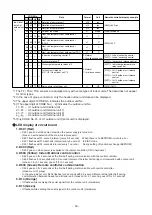
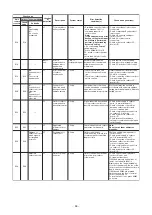
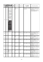
On the remote controller (Wired remote controller
, Centr
al control remote controller) and on the interf
ace P
.C
. board of the ou
tdoor
unit, LCD displa
y
par
t (Remote controller) or
When a troub
le occurred, the method to judge the troub
le or def
ectiv
e
position of the air conditioner b
y
this self-diagnosis fu
nction is sho
w
n belo
w
.
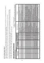
The f
ollo
wing tab
le sho
w
s the list of each chec
k
code that each de
vice detects
. Chec
k
the chec
k contents in the f
o
llo
wing tab
le
according to position to be chec
k
ed.
Chec
k
from the indoor remote controller or
TCC-LINK centr
al controller
: Ref
e
r to
“Displa
y
on remote controller &
TCC-LINK centr
al controller”
in the f
o
llo
wing tab
le
.
Chec
k
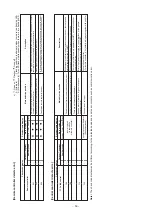
from outdoor unit:
Ref
e
r to
“Displa
y of outdoor segment”
in the f
o
llo
wing tab
le
.
Chec
k from indoor unit of wireless remote controller
: Ref
e
r to Receiver
lamp displa
y”
in the f
o
llo
wing tab
le
.
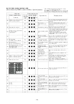
Chec
k code displa
y list (Indoor unit)
[Indoor unit detects err
o
r.
]
(
∗
)
: Goes on,
: Flashes
,
: Goes off
A (Alter
n
ate)
: Flashing condition is alter
n
ate when there are tw
o flashing LED
.
S (Sim
ultaneously)
: T
w
o LED flash sim
u
ltaneously when there are tw
o flashing LED
.
Chec
k
code displa
y
TCC-LINK central
& remote contr
o
ller
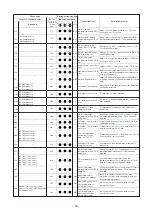
E03
E04
E08
E11
E18
F01
F02
F03
F10
F29
L03
L07
L08
L09
L20
L30
P01
P10
P12
P31
Outdoor 7-segment
A
uxiliar
y code
——
——
E
0
8
D
uplicated indoor unit No
.
——
——
——
——
——
——
——
——
——
L08
—
——
——
L30
D
etected indoor unit No
.
——
P10
Detected indoor unit No
.
——
——
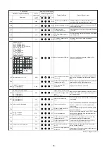
Main def
ective position
Regular comm
u
nication error betw
een indoor
and remote controller
Regular comm
unication error betw
een indoor
and outdoor
Duplicated indoor address
Communication error between Application
control kit and indoor unit
Regular comm
unication error betw
een header
and f
o
llo
w
er in indoor unit
Indoor heat e
x
changer temp
. sensor (TCJ) error
Indoor heat e
xchanger temp
. sensor (TC2) error
Indoor heat e
xchanger temp
. sensor (TC1) error
Room tem.
Sensor (T
A) error
Indoor or other P
.C
. board error
Duplicated setting of header in indoor group
There is g
roup cab
le in individual indoor unit.
Indoor g
roup address is unset.
Indoor capacity is unset.
Duplicated centr
a
l control system address
Exter
nal error was input in indoor (Interloc
k
).
Indoor A
C
f
a
n error
Indoor o
v
erflo
w
w
a
s detected.
Indoor DC f
a
n error
Other indoor unit error
Description
No comm
unication from remote controller and netw
or
k adapter
(No centr
a
l control system communication also)
No comm
unication from outdoor unit
An address same to self address was detected.
Communication error between Application control kit and indoor unit P.C.
board
Regular comm
unication betw
een header and f
o
llo
w
er units in indoor unit
w
a
s impossib
le
.
Open/shor
t of heat e
x
changer temp
. sensor (TCJ) w
as detected.
Open/shor
t of heat e
x
changer temp
. sensor (TC2) was detected.
Open/shor
t of heat e
x
changer temp
. sensor (TC1) was detected.
Open/shor
t of room temp
. sensor (T
A) w
as detected.
Indoor EEPR
OM error (Other error ma
y be detected.)
There w
e
re m
u
ltiple header units in a g
roup
.
There is e
v
en an indoor unit connected to group in individual indoor unit.
Indoor g
roup address is unset.
(Detected also at outdoor unit side)
Capacity of indoor unit is unset.
Setting of central control system address is duplicated.
System abnor
mally stopped b
y
input of e
xter
nal error (CN80).
Error of indoor A
C
can w
as detected.
(F
an motor ther
mal rela
y oper
ation)
Float s
witch oper
a
ted.
Error (Ov
er-current, loc
k
, etc.) of indoor DC f
a
n w
a
s detected.
Group f
o
llo
w
er unit cannot be operated b
y
[E03/L03/L07/L08] alar
m of
header unit.
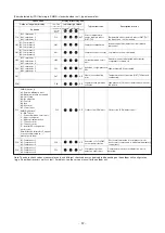
Note)
The chec
k
code displa
y
ma
y be diff
e
rent according to the detected de
vice e
v
en same error contents such as comm
unication error
.
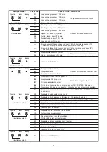
7-
seg
m
e
n
t displa
y par
t (on outdoor interf
ace P
.C
. board) is pro
v
ided in order to displa
y the oper
ation status
.
Receiver lamp displa
y


