– 14 –
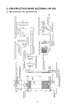
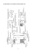
2. CONSTRUCTION VIEWS (EXTERNAL VIEWS)
2-1. MMF-AP0156H-E (TR), AP0186H-E (TR)
Wal
l
(
1
3
0 knock
o
ut
h
o
le
)
(5
0x
120 kno
ckout
hol
e
)
( 8
0
k
n
o
c
k
o
u
t
h
o
le
)
Wa
ll
In
ca
se of
i
n
st
al
lin
g
d
ist
anc
e
is
5
0
m
m
f
ro
m
w
a
ll
(
)
(50x1
2
0 knoc
kout
h
o
le
)
Y
o
u
c
a
n
al
s
o
i
n
s
ta
ll
th
e i
n
s
ta
lla
ti
on
pl
a
te
b
y
re
ve
rs
in
g of
t
h
e
p
lat
e
.
Un
it
c
a
n
b
e
in
s
ta
lle
d
5
0
m
m
apa
rt
f
rom
w
a
ll.
R
e
fr
ig
e
ran
t pi
pi
ng
pos
iti
on
Spa
c
e r
e
qui
red f
o
r
in
s
tal
la
ti
o
n
an
d s
e
rv
ic
in
g
(I
n c
a
s
e
of r
ight
s
id
e
pi
pi
ng
)
Wall
Fl
oor
Fron
t
Wa
ll
Fr
on
t
Wa
ll
Wall
D
e
ta
ils o
f h
o
le
f
o
r b
a
ck sid
e
p
ip
in
g
C L
(
)
(F
or
b
a
c
k
s
ide
p
ipi
n
g
)
There are many holes of two kinds o
n
installation plate,
one is to fix for wall and the other is
to fix for the unit.
Please choose the best holes and
the installation position,
(
)
D
e
tai
ls
o
f ho
le
for
l
o
w
e
r s
ide
pi
pi
ng
(
)
Fo
r
M
8
S
c
re
w
b
o
lt
or
M
8
A
n
ch
or
b
o
lt
(F
or
u
nder
sur
face
pi
pi
n
g
)
Wal
l
1750
Mo
re
than 20
0
20
210
80
30
x
3
600
40
25
210
815
631
59
10
20
In
st
al
la
ti
on pl
at
e
D
isch
a
rg
e por
t
In
st
al
la
ti
on
p
lat
e
Su
c
ti
o
n
p
o
rt
120
165
120
18
0
D
rai
n hose
R
e
fr
ig
er
an
t pi
pi
n
g
hol
e
(B
ack
si
de)
R
e
fr
ig
e
ran
t pi
pi
n
g
hol
e
(B
ot
to
m
si
de)
10
7
50
200
132
157
R
e
fr
ig
e
ra
n
t
pi
pi
ng por
t(
B
ot
h si
d
e
)
10
64
0
10
19
2
105
80
300
42
92
88
L
o
we
r re
fri
g
e
n
ra
n
t p
ip
in
g
p
o
rt
50
Th
e
h
e
ad si
ze of
t
h
e bol
t
to
f
ix shou
ld
sep
a
ra
te
.
358
164
18
1
15
5
100
0
M
o
re
t
h
an
50
0
120
12
0
1770
a
2-
lo
w
e
r hol
e
13
0 knocko
u
t
a
b
105
50
42
88
120
19
2
640
50x1
20(
s
qu
ar
e)
4-
lo
w
e
r ho
le
341
13
5
30
x
3
Co
n
tro
l
co
ver
(B
o
th
s
id
e
)
(G
as si
de)
R
e
fri
g
e
ra
n
t
p
ip
in
g
j
o
in
t
1
2
.7
(L
iq
u
id
s
id
e
)
R
e
fr
ig
e
ra
n
t
pi
pi
ng j
o
in
t
6.
4
F
o
r M8
S
c
re
w
b
o
lt
or
M
8
A
n
ch
or
b
o
lt
In ca
se
of
1730
b
In ca
se
of
and install tightly.
More
th
an
C L

