


Air to Air Heat Exchanger with DX Coil Unit
Installation Manual
EN
Air to Air Heat Exchanger with DX Coil Unit
Installation Manual
– 8 –
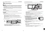
6
Drain Piping Work
CAUTION
Install drain pipes to drain water securely referring
to the Installation Manual. In addition, insulate the
pipes from heat to prevent condensation.
(Inappropriate piping results in water leaking into the
room and furniture may be damaged.)
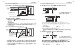
REQUIREMENT
• Install drain pipes to prevent water from leaking.
• Set the drain pipe with downward slope (1/100 or
more), and do not make swelling or trap on the piping.
It may cause an abnormal sound.
• For length of the traversing drain pipe, restrict to 20 m
or less.
In case of a long pipe, provide support brackets with
interval of 1.5 - 2 m in order to prevent waving.
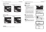
• Set the collective piping as shown in the below figure.
• Do not apply force to the connecting part of the drain
pipe.
• Perform heat insulation of the drain pipes of the indoor
unit.
• Perform heat insulation of the connecting part with the
indoor unit.
An incomplete heat insulation causes dew dropping.
• If the installation place is subject to freezing, perform
anti-freezing work.
Piping/Heat insulating
material
Procure the following materials for piping and heat
insulating locally.
Connecting drain pipe
NOTE
• Connect hard vinyl chloride pipes securely using an
adhesive for vinyl chloride to avoid water leakage.
• It takes some time until the adhesive is dried and
hardened (refer to the manual of the adhesive). Do not
apply stress to the joint with the drain pipe during this
time period.
Drain-up
For the installation instruction of a drain-pump kit (sold
separately), refer to the Installation Manual supplied
with the drain-pump kit.
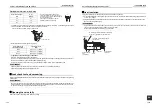
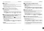
Check the draining
In the test run, check that water drain is properly
performed and water does not leak from the connecting
part of the pipes.
REQUIREMENT
• Check draining also when installed in heating period.
• Using a pitcher or hose, pour water (1500 - 2000 cc)
into the discharge port before installation of the
maintenance cover.
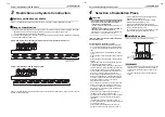
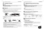
Piping
Hard vinyl chloride pipe VP25 (Outer
dia. : Ø32 mm)
Heat insulator
Foam polyethylene:
Thickness 10 mm or more
maintenance
cover
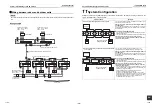
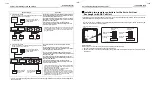
7
Water Supply Piping for a Humidifier
CAUTION
Install the water supply pipes after washing the inside of them with water.
Install a drain valve on the water supply pipe, then drain the water until the drained water runs clear.
Do not to allow cutting fluid or detergent to enter the pipes.
The water quality of the humidifiers supply water should meet public waterworks standards, and have a hardness less
than 100mg/
ℓ
. If the supply water does not meet these standards, use a deionizer.
NOTE
• If the installation place is subject to freezing, perform anti-freezing work.
• Do not connect the water supply pipe directly to the public water pipe. Use a cistern tank (procured locally).
• Use water which meets the following conditions:
• Water pressure: 2×10
4
Pa to 49×10
4
Pa
• Water temperature: 5°C to 40°C
• Attach a service valve or drain valve (procured locally) near the water intake.
While the humidifier is not in operation, the water inside the pipes and cistern tank does not flow and becomes
stagnant.
If the stagnant water is used for water supply in the initial stages of using the humidifier (heater), a smell may come
out or bacteria may multiply.
If you do not use the humidifier for a long time, drain off water from the pipes and from the cistern tank.
Before the season for using the humidifier (heater) arrives, open the drain/water supply valves to exchange the water
inside the pipes.
• Close the water supply valve when the season for using the humidifier (heater) has passed.
• Prevent corrosive gas, salt, or oil mist from entering the air.
• Clean the strainer for water supply when the season for using the humidifier (heater) arrives.
• Fix the water supply pipes so that excessive force is not applied to them.
• Arrange the pipes so that they do not obstruct opening the maintenance cover for the heat transfer element/
humidification element or removing the humidification element.
• Do not allow cutting fluid from being mixed with the supplying water as it causes the humidifying unit or drain pan to
deteriorate. If cutting fluid sticks to it, wash it immediately in a sufficient amount of water.
• Use 2 wrenches, to connect a pipe to a single union pipe joint or to remove it from the single union pipe joint.
• Drain off water from the cistern tank when the humidifier is not used.
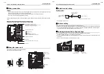
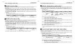
Unit
Heat insulator (for the
water supply pipe)
Water inlet connecting
part size
R1/2
Heat insulator
(for the
strainer)
Service valve
Drain valve
Cap
15-EN
16-EN


