


Air to Air Heat Exchanger with DX Coil Unit
Installation Manual
Air to Air Heat Exchanger with DX Coil Unit
Installation Manual
– 19 –
4
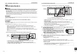
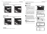
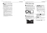
Using TIMER time
/
buttons, select
SET DATA [
].
5
Push
button. When the display changes
from flashing to lit, the setup is completed.
• To change settings of another indoor unit,
repeat from Procedure
2
.
• To change other settings of the selected indoor
unit, repeat from Procedure
3
.
Use
button to clear the settings.
To make settings after
button was pushed,
repeat from Procedure
2
.
6
When settings have been completed, push
button to determine the settings.
When
button is pushed, “SETTING” flashes
and then the display content disappears and the
air conditioner enters the normal stop mode.
(While “SETTING” is flashing, no operation of the
remote controller is accepted.)
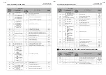
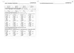
Codes (DN codes) for changing settings
Codes in the table below are necessary for local advanced control.
* Adjusting this setting is necessary for the header unit when using a system equipped with the Air to Air Heat Exchanger
with DX Coil Unit only, and the Air to Air Heat Exchanger with DX Coil Unit with the smallest indoor unit address number
when using a system equipped with the Air to Air Heat Exchanger with DX Coil Unit and air conditioners.
Code
Description
SET DATA and description
Factory default
Note
01
Lighting-up hours of
the Filter Sign
0000: None
0001: 150 H
0002: 2500 H
0003: 5000 H
0004: 10000 H
0002: 2500 H
Adjusting this setting is
necessary for the
header unit.
31
Single operation of
the fan
0000: Invalid
0001: Valid
ON/OFF operation for the Air to Air Heat
Exchanger with DX Coil Unit only
0000: Invalid
Adjusting this setting is
necessary for the
header unit. (System
equipped with the Air to
Air Heat Exchanger
with DX Coil Unit and
air conditioners)
48
Unbalanced
ventilation Fan
speed
0000: Normal
0001: SA (High) > EA (Low) active
0002: SA (Low) < EA (High) active
* “High” may be “Extra High”.
0000: Normal
Adjusting this setting is
necessary for all the Air
to Air Heat Exchanger
with DX Coil Units in
the group.
4C
Nighttime heat
purge
0000: Invalid
0001-0048: Start after [Setting value] x 1
hour(s)
* Setting for the time before the nighttime
heat purge operation starts
0000: Nighttime
heat purge
OFF
Adjusting this setting is
necessary for all the Air
to Air Heat Exchanger
with DX Coil Units in
the group. (System
equipped with the Air to
Air Heat Exchanger
with DX Coil Unit and
air conditioners)
4E
Setting of the linked
operation with
external devices
0000: ON/OFF linked
0001: ON linked
0002: OFF linked
* Specifies whether the ON/OFF
operation of the Air to Air Heat
Exchanger with DX Coil Unit is linked
with the external device operation
0000: ON/OFF
linked
Adjusting this setting is
necessary for a Air to
Air Heat Exchanger
with DX Coil Unit to
which an adapter for
remote ON/OFF control
(sold separately) is
connected.
EA
Changing the
ventilation mode
0002: Heat Exchange mode
0003: Automatic mode
* Compatible with systems without a
remote controller and RBC-AMT32E
0003: Automatic
mode
*1
EB
Changing the
ventilation Fan
speed
0002: High
0003: Low
0004: Unbalanced
* “High” may be “Extra High”.
* Compatible with systems without a
remote controller and RBC-AMT32E
0002: High
*1
ED
Changing the
operation output
0000: ON during normal operation
0001: ON during normal operation or
nighttime heat purge operation
0002: ON during nighttime heat purge
operation
0003: ON when SA fan is running
0004: ON when EA fan is running
0000: ON during
normal
operation
Adjusting this setting is
necessary for a Air to
Air Heat Exchanger
with DX Coil Unit which
transfers the operation
output.
EE
Changing the
abnormal signal/
Bypass mode
signal output
0000: ON when an abnormal signal is
detected
0001: ON when the Bypass mode signal is
detected
0000: ON when an
abnormal
signal is
detected
Adjusting this setting is
necessary for a Air to
Air Heat Exchanger
with DX Coil Unit which
transfers the operation
output.
37-EN
38-EN


