


– 29 –
Air to Air Heat Exchanger with DX Coil Unit
Installation Manual
Air to Air Heat Exchanger with DX Coil Unit
Installation Manual
H06
H06
—
zzz
Low pressure protective operation
I/F
H07
H07
—
d7
Low oil level protection
I/F
H08
H08
01: TK1 sensor error
02: TK2 sensor error
03: TK3 sensor error
04: TK4 sensor error
d4
Thermo sensor for oil level detection error
I/F
H14
H14
—
44
Compressor 2 case thermostat operation
I/F
H16
H16
01: TK1 oil circuit
system error
02: TK2 oil circuit
system error
03: TK3 oil circuit
system error
04: TK4 oil circuit
system error
d7
Oil level detection circuit error
I/F
L02
—
—
—
Outdoor unit model unmatch error
Indoor
L03
—
—
96
Header indoor units are duplicated.
Indoor
L04
L04
—
96
Outdoor unit addresses are duplicated.
I/F
L05
—
—
96
Prior indoor units are duplicated. (Displayed on the prior
unit)
I/F
L06
L06
The number of prior indoor
units
96
Prior indoor units are duplicated. (Displayed on the units
other than the prior ones)
I/F
L07
—
—
99
Group line in individual indoor unit
Indoor
L08
L08
—
99
Indoor group address unset
Indoor
I/F
L09
—
—
46
Indoor unit capacity unset
Indoor
L10
L10
—
zzz
Outdoor unit capacity unset
I/F
L20
—
—
zzz
Central control addresses are duplicated.
AINET
Indoor
L26
L26
●●●
The number of units
46
Exceeding the number of units to connect
I/F
L27
L27
●●●
The number of units
46
Error with the number of units to connect
I/F
L28
L28
—
46
Exceeding the number of outdoor units to connect
I/F
L29
L29
01: Problem with A3-
IPDU1
02: Problem with A3-
IPDU2
03: Problem with A3-
IPDU1 and A3-
IPDU2
04: Problem with the
fan IPDU
05: Problem with A3-
IPDU1 and the fan
IPDU
06: Problem with A3-
IPDU2 and the fan
IPDU
07: Problem with all
IPDUs
CF
Error with the number of IPDU
I/F
L30
L30
Detected indoor unit address
zzz
Indoor/outdoor unit interlock
Indoor
—
L31
—
—
Extended IC error
I/F
P03
P03
—
1E
TD1 discharge temperature error
I/F
P04
P04
01: Compressor 1 side
02: Compressor 2 side
21
High pressure switch system operation
IPDU
P05
P05
01: Phase loss
detected
02: Phase order error
AF
Phase loss is detected or phase order error.
I/F
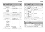
Wired
remote
controller
display
Error code
Error code name
Judging
device
7 segment display on the
outdoor unit
AI-NET
central
controller
display
Auxiliary code
Problems detected by TCC-LINK central remote controller
P07
P07
01: Compressor 1 side
02: Compressor 2 side
1C
Heat sink overheat
IPDU
I/F
P09
P09
Detected thermal storage
address
47
Thermal storage unit water shortage
Thermal
storage
P10
P10
Detected indoor unit address
0b
Indoor unit water overflow
Indoor
P13
P13
—
47
Outdoor liquid back detection error
I/F
P15
P15
01: TS condition
02: TD condition
AE
Gas leakage detection
I/F
P17
P17
—
bb
TD2 discharge temperature error
I/F
P19
P19
Detected outdoor unit
number
08
4-way valve inverse error
I/F
P20
P20
—
22
High pressure protective operation
I/F
P22
P22
04: Rotation difference
error
06: Exceeding
maximum rotation
speed
08: Synchronazation
lost
0A: IDC operation
0C: Ventilation lock
0D: Lock
0E: Synchronization
error
0F: Brake error
1A
Outdoor fan IPDU error
IPDU
P26
P26
01: Compressor 1 side
02: Compressor 2 side
14
G-TR short circuit protection error
IPDU
P29
P29
01: Compressor 1 side
02: Compressor 2 side
16
Compressor position detection circuit error
IPDU
P31
—
—
47
Other follower indoor units error
Indoor
—
—
—
b7
Indoor group error
AINET
—
—
—
97
AI-NET communication error
AINET
—
—
—
99
Network adapters are duplicated.
AINET
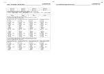
Wired
remote
controller
display
Check code
Checking code name
Judging
device
7 segment display on the
outdoor unit
AI-NET
central
controller
display
Auxiliary code
C05
—
—
—
TCC-LINK central remote controller transmission error
TCC-LINK
C06
—
—
—
TCC-LINK central remote controller receiving error
TCC-LINK
C12
—
—
—
Collective alarm of general-purpose machine control
interface
Multi purpose
equipment
I/F
P30
Varies depending on the error details of the alarm unit
Group-controlled follower unit error
TCC-LINK
—
—
(L20)
Central control addresses are duplicated.
Wired
remote
controller
display
Error code
Error code name
Judging
device
7 segment display on the
outdoor unit
AI-NET
central
controller
display
Auxiliary code
57-EN
58-EN


