


SMMS Slim Duct Type
Installation Manual
EN
SMMS Slim Duct Type
Installation Manual
– 18 –
Filter sign setting
According to the installation condition, the filter sign
term (Notification of filter cleaning) can be changed.
Follow to the basic operation procedure
(
1
→
2
→
3
→
4
→
5
→
6
).
• For the CODE No. in Procedure
3
, specify [01].
• For the [SET DATA] in Procedure
4
, select the SET
DATA of filter sign term from the following table.
To secure better effect of
heating
When it is difficult to obtain satisfactory heating due to
installation place of the indoor unit or structure of the
room, the detection temperature of heating can be
raised. Also use a circulator or other machinery to
circulate heat air near the ceiling.
Follow to the basic operation procedure
(
1
→
2
→
3
→
4
→
5
→
6
).
• For the CODE No. in Procedure
3
, specify [06].
• For the set data in Procedure
4
, select the SET
DATA of shift value of detection temperature to be
set up from the following table.
Remote controller sensor
The temperature sensor of the indoor unit senses room
temperature usually. Set the remote controller sensor
to sense the temperature around the remote controller.
Select items following the basic operation procedure
(
1
→
2
→
3
→
4
→
5
→
6
).
• Specify [32] for the CODE No. in Procedure
3
.
• Select the following data for the SET DATA in
Procedure
4
.
When
flashes, the remote controller sensor is
defective.
Select the SET DATA [0000] (not used) or replace the
remote controller.
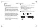
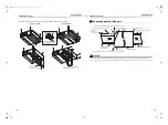
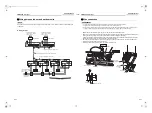
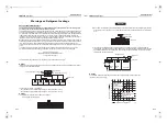
Group control
In a group control, a remote controller can control up to
maximum 8 units.
• The wired remote controller only can control a group
control. The wireless remote controller is unavailable
for this control.
• For wiring procedure and wires of the individual line
(Identical refrigerant line) system, refer to “Electrical
Connection” in this Manual.
• Wiring between indoor units in a group is performed
in the following procedure.
• Connect the indoor units by connecting the remote
controller wires from the remote controller terminal
blocks (A, B) of the indoor unit connected with a
remote controller to the remote controller terminal
blocks (A, B) of the other indoor unit. (Non-polarity)
• For address setup, refer to the Installation Manual
attached to the outdoor unit.
SET DATA
Filter sign term
0000
None
0001
150 H
0002
2500 H
(Factory default)
0003
5000 H
0004
10000 H
SET DATA
Detection temperature shift value
0000
No shift
0001
+1 °C
0002
+2 °C
(Factory default)
0003
+3 °C
0004
+4 °C
0005
+5 °C
0006
+6 °C
SET DATA
0000
0001
Remote controller
sensor
Not used
(Factory default)
Used
10
Test Run
Before test run
• Before turning on the power supply, carry out the
following procedure.
1) By using 500 V-megger, check that resistance
of 1 M
Ω
or more exists between the terminal
block L to N and the earth (grounding).
If resistance of less than 1 M
Ω
is detected, do
not run the unit.
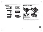
2) Check the valve of the outdoor unit being
opened fully.
• To protect the compressor at activation time, leave
power-ON for 12 hours or more before operating.
• Do not press the electromagnetic contactor to
forcibly perform a test run. (This is very dangerous
because the protective device does not work.)
• Before starting a test run, set addresses by following
the Installation Manual supplied with the outdoor
unit.
Execute a test run
• When a fan operation is to be performed for an
individual indoor unit, turn off the power, short CN72
on the circuit board, and then turn the power back
on. (First set the operating mode to “fan,” and then
operate.) When the test run has been performed
using this method, do NOT forget to release the
shorting of CN72 after the test run is completed.
Operate the unit with the wired remote controller as
usual.
For the procedure of the operation, refer to the
attached Owner’s Manual to the outdoor unit.
A forced test run can be executed in the following
procedure even if the operation stops by thermostat-
OFF.
In order to prevent a serial operation, the forced test
run is released after 60 minutes have passed and
returns to the usual operation.
CAUTION
Do not use the forced test run for cases other than the
test run because it applies an excessive load to the
devices.
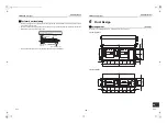
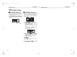
Wired remote controller
1
Push
button for 4 seconds or more.
[TEST] is displayed on the display part and
the selection of mode in the test mode is
permitted.
2
Push
button.
3
Select the operation mode with
button, [
Cool] or [
Heat].
• Do not run the air conditioner in a mode other
than [
Cool] or [
Heat].
• The temperature controlling function does not
work during test run.
• The detection of error is performed as usual.
4
After the test run, push
button to
stop a test run.
(Display part is same as procedure 1.)
5
Push
check button to cancel (release
from) the test run mode.
([TEST] disappears on the display and the status
returns to a normal.)
2, 4
3
1,5
35-EN
36-EN
+00EH99879301_01EN.book Page 18 Tuesday, March 15, 2011 8:42 PM


