


SMMS Slim Duct Type
Installation Manual
EN
SMMS Slim Duct Type
Installation Manual
– 14 –
8
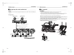
Electrical Connection
WARNING
•
Use the specified wires for wiring connect the
terminals. Securely fix them to prevent external
forces applied to the terminals from affecting the
terminals.
Incomplete connection or fixation may cause a fire or
other trouble.
•
Connect earth wire. (grounding work)
Incomplete grounding cause an electric shock.
Do not connect earth wires to gas pipes, water pipes,
lightning conductor or telephone earth wires.
•
Appliance shall be installed in accordance with
national wiring regulations.
Capacity shortage of power circuit or incomplete
installation may cause an electric shock or a fire.
CAUTION
• If incorrect / incomplete wiring is carried out, it will
cause an electrical fire or smoke.
• Install an earth leakage breaker that is not tripped by
shock waves.
If an earth leakage breaker is not installed, an electric
shock may be caused.
• Use the cord clamps attached to the product.
• Do not damage or scratch the conductive core and
inner insulator of power and inter-connecting wires
when peeling them.
• Use the power cord and Inter-connecting wire of
specified thickness, type, and protective devices
required.
• Do not connect 220 V – 240 V power to the terminal
blocks (
,
,
,
) for control wiring. (Otherwise,
the system will fail.)
• Do not damage or scratch the conductive core and
inner insulator of power and inter-connecting wires
when peeling them.
• Perform the electric wiring so that it does not come to
contact with the high-temperature part of the pipe.
The coating may melt resulting in an accident.
REQUIREMENT
• For power supply wiring, strictly conform to the Local
Regulation in each country.
• For wiring of power supply of the outdoor units, follow
the Installation Manual of each outdoor unit.
• Perform the electric wiring so that it does not come to
contact with the high-temperature part of the pipe.The
coating may melt resulting in an accident.
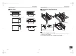
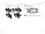
• After connecting wires to the terminal blocks, provide
a trap and fix wires with the cord clamp.
• Run the refrigerant piping line and control wiring line in
the same line.
• Do not turn on the power of the indoor unit until
vacuuming of the refrigerant pipes completes.
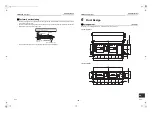
Power supply wire and
communication wires
specifications
Power supply wire and communication wires are
procured locally.
For the power supply specifications, follow to the table
below. If capacity is little, it is dangerous because
overheat or burnout may be caused.
For specifications of the power capacity of the outdoor
unit and the power supply wires, refer to the Installation
Manual attached to the outdoor unit.
Indoor unit power supply
• For the power supply of the indoor unit, prepare the
exclusive power supply separated from that of the
outdoor unit.
• Arrange the power supply, circuit breaker, and main
switch of the indoor unit connected to the same
outdoor unit so that they are commonly used.
• Power supply wire specification: Cable 3-core 2.5
mm²,
in conformity with Design 60245 IEC 57
.
U
1
U
2
A
B
▼
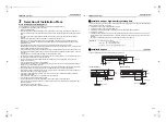
Power supply
Control wiring, Central controller wiring
• 2-core with polarity wires are used for the Control wiring between indoor unit and outdoor unit and Central
controller wiring.
• To prevent noise trouble, use 2-core shield wire.
• The length of the communication line means the total length of the inter-unit wire length between indoor and
outdoor units added with the central control system wire length.
▼
Communication line
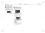
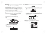
Remote controller wiring
• 2-core with non-polarity wire is used for wiring of the remote controller wiring and group remote controllers wiring.
CAUTION
The remote controller wire (Communication line) and AC 220 – 240 V wires cannot be parallel to contact
each other and cannot be stored in the same conduits. If doing so, a trouble may be caused on the control
system due to noise or other factor.
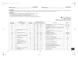
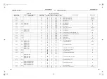
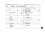
Power supply
220 V – 240 V ~, 50 Hz
220 V ~, 60 Hz
Power supply switch / circuit breaker or power supply wiring / fuse rating for indoor units should be selected by the
accumulated total current values of the indoor units.
Power supply wiring
Below 50 m
2.5 mm
2
Control wiring between indoor units, and
outdoor unit (2-core shield wire)
Wire size
(Up to 1000 m) 1.25 mm²
(Up to 2000 m) 2.0 mm²
Central control line wiring (2-core shield
wire)
Wire size
(Up to 1000 m) 1.25 mm²
(Up to 2000 m) 2.0 mm²
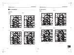
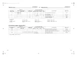
Remote controller wiring, remote controller inter-unit
wiring
Wire size: 0.5 mm² to 2.0 mm²
Total wire length of remote controller wiring and remote
controller inter-unit wiring = L + L1 + L2 + … Ln
In case of wired type only
Up to 500 m
In case of wireless type
included
Up to 400 m
Total wire length of remote controller inter-unit wiring = L1 + L2 + … Ln
Up to 200 m
L1
L
L2
Ln
Indoor unit
Remote controller inter-unit wiring
Indoor unit
Indoor unit
Indoor unit
Remote
controller
(Max. 8 units)
Remote
controller
wiring
27-EN
28-EN
+00EH99879301_01EN.book Page 14 Tuesday, March 15, 2011 8:42 PM


