13
8
SETUP OF OUTDOOR UNIT
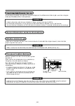
When using PMV Kit on the Mini-SMMS system, it is necessary to set up DIP switches on the
interface P.C. board of the outdoor unit.
• Corresponding outdoor units: MCY-MAP0401HT
✻
✻
✻
✻
✻
, MCY-KAP0501HT
✻
✻
✻
✻
✻
, MCY-MAP0601HT
✻
✻
✻
✻
✻
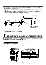
How to set up
• Turn DIP switch [SW08] on the interface P.C. board of the outdoor unit to ON side.
7
ELECTRIC WORK
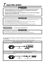
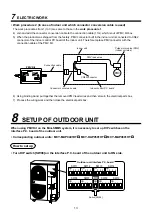
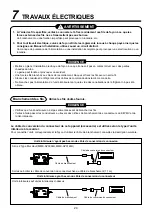
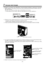
• Work procedure 2 (In case of indoor unit which connector conversion cable is used)
The work procedures from 1) to 3) are same to those in the work procedure 1.
4) Join and add the connector conversion cable to the connection cable (11m) which is out of PMV Kit box.
5) When the product was shipped from the factory, PMV connector built in the indoor unit is connected to CN82
connector of the indoor control PC board of the indoor unit. Therefore replace PMV connector with the
connection cable of the PMV Kit.
6) Using binding band, put together the removed PMV lead wires and then store in the electrical parts box.
7) Process the wiring work and then close the electrical parts box.
PMV
PMV Kit
Indoor unit
CN82 connector
Connector conversion cable
Indoor control P.C. board
Connection cable
PMV lead wires
Pulse motor valve (PMV)
(Indoor unit side)
SW11
1
ON
2 3 4
SW12
1
ON
2 3 4
SW06
1
ON
2 3 4
SW07
1
ON
ON
ON
ON
2 3 4
SW09
SW08
1
1
2 3 4
SW10
1 2 3 4
SW13
1
ON
2 3 4
SW14
1
ON
2 3 4
Outdoor unit interface P.C. board
Switch [SW08]


