background image

Installing and Removing Hardware

Power Supply Unit

71

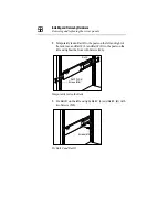
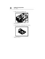
Connect the power cable and signal cable.

Connecting the cables

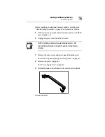
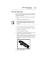
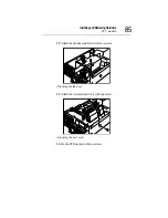
Install the power supply unit, slide back slightly and fix it with 

six screws.

Installing the power supply unit

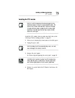
Attach the server panels and outer covers.

Содержание Magnia Z300

Страница 1: ...MAGNIA Z300 User sGuide ...

Страница 2: ...ence in which case the user will be required to correct the interference at his own expense NOTE Only peripherals complying with the FCC Class A limits may be attached to this computer Shielded cables must be used between the external devices and the computer s parallel port PS 2 keyboard port PS 2 mouse port and monitor port Changes or modifications made to this equipment not expressly approved b...

Страница 3: ...ngLabel Some warning labels are attached to units of this equipment as shown below Read these labels carefully for safe use of this equipment power supply unit System Unit power supply unit External Unit 1 2 ...

Страница 4: ...1 2 ...

Страница 5: ... not try to open the enclosure Use of controls or adjustments or performance of proce dures other than those specified in the owner s manual may result in hazardous radiation exposure Copyright This guide is copyrighted by Toshiba Corporation with all rights reserved Under the copyright laws this guide cannot be reproduced in any form without the prior written permission of TOSHIBA No patent liabi...

Страница 6: ...ARISING OUT OF OR IN CONNECTION WITH THIS MANUAL OR ANY OTHER INFORMATION CONTAINED HEREIN OR THE USE THEREOF Trademarks MAGNIA is a trademark of TOSHIBA Corporation Pentium and LANDesk are registered trademarks of Intel Corporation PS 2 is a trademark of International Business Machines Corporation MS Microsoft and its logos MS DOS Windows and Windows NT are regis tered trademarks or trademarks of...

Страница 7: ...tere Informationen Das Produkt entspricht den Anforderungen der Niederspan nungs Richtlinie 73 23 EG und der EMC Richtlinie 89 336 EG Informations complémentaires Ce produit est conforme aux exigences de la directive sur les basses tensions 73 23 CEE et de la directive EMC 89 336 CEE Información complementaria El Producto cumple los requistos de baja tensión de la Directiva 73 23 CEE y la Directiv...

Страница 8: ......

Страница 9: ...t 66MHz PCI slot c Main memory expandable to a maximum of 3 GB c 24 speed CD ROM drive as standard c Up to two 76 GB hard disk drives IDE c IDE RAID as standard RAID 0 and 1 c Hot swap hard disk drives c Ultra 160 SCSI IF c 2 LAN ports 100BASE TX provided as standard ALB Adaptive Line Balance and AFT Adaptive Fault Tolerance compatible c Wireless LAN IEEE802 11b card option can be mounted ...

Страница 10: ...Device Bay Unit Z1 NOTE The MAGNIA Z300 meets the FCC regulations for a Class A digital device suitable for use in a business installation There is a possibility of radio interference when using the MAGNIA Z300 in a home environment Aboutthisguide This guide introduces the features of the MAGNIA Z300 and explains how to set up configure and maintain the server Before using the MAGNIA Z300 server p...

Страница 11: ...tions as follows DANGER This icon indicates the existence of a hazard that could result in death or serious bodily injury if the safety instruction is not observed CAUTION This icon indicates the existence of a hazard that could result in damage to equipment or property if the safety instruction is not observed WARNING This icon indicates the existence of a hazard that could result in bodily injur...

Страница 12: ...ntation CD ROM contains the technical information about how the server works c Harness Eye web User s Guide on the Documentation CD ROM contains Harness Eye web settings and operation meth ods Harness Eye web runs on Windows NT Server Version 4 0 Windows 2000 Server and Linux c The Toshiba Server Setup Tool User s Guide on the Docu mentation CD ROM contains instructions for setting up and optimizi...

Страница 13: ...round its war ranty programs See the warranty and service material included with the server for registration information Maintenancecontracts Periodic maintenance and inspection is essential for keeping the server fully operational and assuring its safe use Toshiba recom mends taking out a maintenance contract for this purpose ...

Страница 14: ......

Страница 15: ...icroTowerType RackType 5 MicroTowerType 7 RackType 8 Powerrequirements 9 Frontview withthefrontpanelclosed 10 Keylock 10 Frontview withthefrontpanelopened 11 1 Frontpanel 11 2 Operationbuttons 12 3 Systemstatusindicators 14 4 Frontpaneldisplay 16 5 Cardslot 18 6 USB1connector 18 7 USB2connector 18 8 Devicebay 18 9 HDD LANstatusindicators 19 ...

Страница 16: ...peripheraldevices 26 Floppydiskdrive 29 Maintenance 30 Maintenanceoftheserver 30 Maintenanceofthekeyboard 30 Maintenanceofthedisplayunit 30 Connectingthepowercable 31 Switchingontheserver 33 Turningontheserverintheusualprocess 33 Turningontheserverbythe RemoteManagement function 34 POST PowerOnSelf Test 34 Startingupthesystem 35 Startingupwiththefloppydisk 35 Startingupbytheharddiskdriveunit inthe...

Страница 17: ...evice 52 Removingandreplacingtheserverpanels 54 Replacingthetoppanels forMicroTowerTypes 55 Removing replacingthetoppanel forRackTypes 55 WhenusingaRackType 56 PowerSupplyUnit 69 Removingthepowersupplyunit 69 Installingthepowersupplyunit 70 Memorymodule 72 Installinganadditionalmemorymodule 74 Removingamemorymodule 77 CPUmodule 78 InstallingtheCPUmodule 79 ReplacingtheCPUmodule 87 Internalbattery ...

Страница 18: ...itcontrolconnectorIN OUT 117 2 SCSIconnector 117 InstallingandRemovingHardDiskDrive HDD SCSIHDD 118 Installingtheharddiskdrive 118 Replacingaharddiskdriveduringoperation 120 Setupofdiskarray RAID 124 FrontviewoftheExternalDeviceBayUnitZ1 withthefrontpanel closed 125 Keylock 125 FrontviewoftheExternalDeviceBayUnitZ1 withthefrontpanel opened 126 1 Frontpanel 126 2 Powerbutton 127 3 Systemstatusindic...

Страница 19: ...dFrontPanelDisplaySetupTool 156 Howtostartupandoperatethesetuptool 156 ConfiguringMegaRAIDIDE 160 ConfiguringMegaRAIDIDE 160 UsingtheMegaRAIDIDESetupUtility 163 SwitchWindows TAB 165 AutoConfigureStripe F1 165 AutoConfigureMirror F2 165 CreateArray F4 166 DeleteArray F5 169 RestoreOldConfiguration F6 169 EditOptions F7 169 SaveandExit F10 170 Chapter5 InstallingSoftware 172 WindowsNT Server4 0 172...

Страница 20: ...shooting 204 Troubleshooting 204 Youcanhearabnormalnoiseorsmellfoulodours andheara continuousbuzzer 204 Nothinghappensifyoupressthepowerswitch Or nothingappears onscreeneventhoughyoucanheartheserverrunning 205 Charactersaredistortedornotdisplayedproperly 206 Thesystemstatusindicatorsanddiskstatusindicatorsturnon abnormally 206 ThediskandSTSindicatorslightandflashamber 207 Thefaultindicatorlightsam...

Страница 21: ... 219 AppendixB Interfaces 222 RGBinterface 222 RGBinterfacesynchronizingsignals 223 Serialinterface 224 Keyboard mouseinterface 225 LAN 1 2interface 226 USB 1 2interface 226 Expansionslots 64bit 66MHzPCIslot 227 AppendixC SwitchSetting 232 Hardwaresetupinformation 232 RecoveryBoot 233 AppendixD TroubleInformation 238 AppendixE UnitLogs 244 Unitlogs 244 Basicsystemconfiguration 245 CPUs 245 Memorie...

Страница 22: ...xxii ...

Страница 23: ...nt panel closed 10 Front view with the front panel opened 11 Rear view 22 Inside the server 25 Maintenance 30 Connecting the power cable 31 Switching on the server 33 POST Power On Self Test 34 Starting up the system 35 BIOS setup 37 Making a floppy disk 38 Setup of system configuration 39 Setup of disk array RAID 40 Installing software 41 Switching off the server 42 ...

Страница 24: ...server and to have it ready for use Checking the items included with the server Check the items in the package according to the accompanying Read Me First Addendum If any of the items is missing or damaged please contact your Toshiba dealer as soon as possible ...

Страница 25: ...also be incorporated with the standard accessories listed However in such a case it is possible that the quantities of some accessories e g brack ets do not agree with those specified on the list this is because they have already been used to fix the optional inter nal device If in contrast an expansion slot panel etc has been removed from the server in order to install an optional device instead ...

Страница 26: ...u have purchased an optional internal device together with the server install it before setting up the server See Installing removing an optional device on page 52 If you find it difficult to install an optional device yourself always ask an authorized MAGNIA service provider to do it for you ...

Страница 27: ...Do not install in locations susceptible to large temperature or humidity changes or near an air conditioner air vent cooling fan heater or heat source Do not install in location where liquids or corrosive chemi cals are stored WARNING If any foreign matter including water has gone into the server perform the shutdown steps immediately turn off the power button and unplug the power cable from the w...

Страница 28: ...to 32 C Rack Type Ambient humidity 30 to 80 Rh No condensation NOTE To avoid condensation when the room temperature is too high or too low do not start your server for about one hour after the room temperature has fallen within a range of 50 to 95 F 10 to 35 C or 50 to 89 F 10 to 32 C if your server is a Rack Type Keep the server free from condensation during use and stor age ...

Страница 29: ...eave enough space around the server for maintenance and ventilation Minimum clearances required for horizontal installation Minimum clearances required for vertical installation 8 inches 20cm or more 12 inches 30cm or more 12 inches 30cm 8 inches 20cm or more or more ...

Страница 30: ...en stacked horizontally Rack Type c Use the optional Toshiba rack and rack mount kit to install a Rack Type c Leave a clearance of more than 24 inches 60 cm before and behind the rack to ensure good ventilation around the server Minimum clearances for installation 24 inches 60cm or more 24 inches 60cm or more ...

Страница 31: ... To ensure the server is securely grounded always use the power cable supplied with the server For wiring in the rack use an optional AC multi tap recommended by Toshiba WARNING Do not use any power cable other than the one supplied with the server The use of an improper power cable may result in a fire Do not use any optional part other than a genuine Toshiba parts or those parts recommended by T...

Страница 32: ...y lock The front panel can be locked in two ways full access and no access depending on the direction of the keyhole Key lock Front panel display Display change button USB 1 connector USB 2 connector Key lock CD ROM drive Power indicator Disk indicator Auto shutdown indicator Fault indicator System status indicator Full access No access ...

Страница 33: ... panel The front panel can be opened by releasing the key lock and push ing its upper center and detached by unhooking its hinges Opening the front panel 1 Front panel 7 USB 1 8 USB 2 2 CD ROM drive 4 System status indicators 3 Operation buttons 5 Front panel 6 Card slot 10 HDD LAN display connector connector status indicators 9 Device bay ...

Страница 34: ... view with the front panel opened 12 Removing the front panel 2 Operation buttons The server has 4 operation buttons on the front panel Operation buttons Power sleep button Reset button NMI button Display change button NMI ...

Страница 35: ...the server to start up OFF Enabling the auto shutdown function If you hold your finger continuously for four sec onds or more and take your finger away the OS is shut down and the power supply is turned off If you take your finger away within four seconds the power is not turned off Disabling the auto shutdown function If you press once and take your finger away the power is turned off Sleep On OS...

Страница 36: ... on the front panel System status indicators Indicator Status Meaning Power Off Out of operation AC power not supplied Litamber Out of operation AC power supplied Lit green In operation Disk Off Out of operation Flashing green Built in disk drive in operation Power indicator Disk indicator Auto shutdown indicator Fault indicator ...

Страница 37: ...r Auto Shutdown is used on Windows NT Windows 2000 or Linux and the Auto Shutdown function is not installed Auto Shutdown is used on Windows NT Windows 2000 or Linux the Auto Shutdown function is installed and set to Disabled 1 Windows NT Windows 2000 or Linux is booting An operating system other than Windows NT or Win dows 2000 or Linux is running Fault Off One of the following modes Out of opera...

Страница 38: ...Example PentiumIII xm m number of CPUs ExDisk xn n number of External Hard Drive Unit Z1s ExBay xi i number of External Device Bay Unit Z1s The number of unit is reflected after power is on 2 User messages In HarnessEye web there are two screens for user messages Panel display 1 and Panel display 2 One of these is dis played Messages can be set by Panel display 1 Warning notices are displayed by P...

Страница 39: ...hen the trouble information exceeds 16 characters the dis play can be scrolled to display all the information Display and meaning See AppendixD on page 237 Display example Holding down the display change button for at least four sec onds displays the user message or system configuration Also holding down the button for at least four seconds with the user messageorsystemconfigurationdisplayeddispla...

Страница 40: ...ton for at least four sec onds displays the user message or system configuration 5 Card slot The card slot accepts an optional wireless LAN card 6 USB1 connector Used to connect a USB device 7 USB2 connector Used to connect a USB device 8 Device bay Used to install up to two hard disk drives Now shutting down system ...

Страница 41: ...tatus indicators Indicator Status Meaning ACT 1 LAN1 Out Data transfer 10Mbps or 100Mbps is not in progress on network Lit green Data transfer 10Mbps or 100Mbps is in progress on network LNK 1 LAN1 Out Network communications 10Mbps or 100Mbps is not possible Lit green Network communications 10Mbps or 100Mbps is possible ACT 2 LAN2 Out Data transfer 10Mbps or 100Mbps is not in progress on network L...

Страница 42: ...ing amber The disk array is being rebuilt PWR 1 HDD1 Off No hard disk drive is installed No power is supplied to theharddisk drive Lit green Power is supplied to the hard disk drive STS 2 HDD2 Off No hard disk drive is installed No data is being read or written Lit green Data is being read or written Lit amber Trouble has occurred Flashing amber The disk array is being rebuilt PWR 2 HDD2 Off No ha...

Страница 43: ...s special techniques and knowledge So instead of installing or replac ing it yourself ask an authorized MAGNIA service provider for assistance An error performed during installation or replacement espe cially when the system is running might result in a system failure and or the corruption or loss of important data and pro grams Keep hard disk drives free from shock and vibration espe cially when ...

Страница 44: ...r view of the server 1 AC connector Used to connect the AC power cable See Connecting the power cable on page 31 2 Security Loop It is possible to attach chains etc to prevent the server from theft 1 AC connector 2 Security Loop Security Loop ...

Страница 45: ...ector 2 Used to connect a 100BASE T or 10BASE T 5 RGB connector Used to connect a display 6 Serial connector Used to connect an RS 232C compliant device 7 External unit control connector Used to connect the external unit 8 SCSI connector Used to connect the SCSI cable See How to connect peripheral devices on page 26 8 SCSI connector 7 External unit control connector 3 LAN 1 connector 1 4 LAN 2 con...

Страница 46: ...n cards 64 bit 66 MHz PCI slot LAN status indicators Indicator Status Meaning Link Lit green Connected successfully Off Network cable not connected or incor rectly connected Activity Lit green Data being transferred Off No active Link Activity LAN 2 connector LAN 1 connector Link Activity ...

Страница 47: ...main board can contain 2 CPU modules and 3 memory mod ules at the maximum 2 SCSI riser card The SCSI riser card has 1 PCI expansion slot half length cards only 1 Motherboard 2 SCSI riser card 3 Cooling fans 4 CPU sockets 5 Memory slots 6 Expansion slot 7 IDE HDD Cage 8 Board for wireless card ...

Страница 48: ...iser card The slot is compliant with PCI 2 2 standard See Expansion cards on page 103 7 IDE HDD cage The IDE HDD cage supports up to two hot swap hard disk drives 8 Board for wireless card The board for wireless card can contain 1 wireless LAN card Connecting peripheral devices How to connect peripheral devices There are USB connectors for connecting USB devices such as FDD and so on on the front ...

Страница 49: ...e server and external units are turned off 2 If the power cables of the server and external units are con nected to an AC outlet pull the plug of the power cable out of the AC outlet 3 Connect each of the peripheral devices to a proper connector on the server with an interface cable Insert the connectors to the correct ports on the server Use the serial converter cable on the serial interface Conn...

Страница 50: ...ing sure that all the peripheral units are properly con nected plug the power cables of the server and peripheral units into AC outlets WARNING When connecting optional units be sure to use genuine Toshiba parts or those recommended by Toshiba If something other is connected to the server it may cause an outbreak of fire For details of optional parts contact an authorized MAGNIA service provider ...

Страница 51: ...ticle about its compatibility to this server When connecting peripheral units see to instructions of respective units together with this manual Floppy disk drive The floppy disk drive FDD supports two floppy disk formats 3 5 2HD 1 44 MB and 3 5 2DD 720 KB NOTE The FDD indicator is lit while data is being read or written When it is lit do not turn off the server nor press the eject button nor reset...

Страница 52: ...is dropped or knocked against other objects it may cause a failure or malfunction of the server Maintenance of the keyboard If dust has accumulated in crevices in the keyboard it may cause malfunction of the keyboard Clean the keyboard according to the following procedure 1 Shut down the server to cut off the power supply to the key board 2 Remove dust between the keys using a vacuum cleaner 3 Cle...

Страница 53: ...nexpected shut down or power failure After connection of peripheral devices is complete connect the power cable to this server following the procedure mentioned below 1 Connect the power cable to the connector on the back of the server Connecting the power cable 2 Plug the power cable into an AC outlet or the power output connector of an uninterruptible power supply UPS ...

Страница 54: ...reak of fire or electric shock When connecting and disconnecting the power cable hold the plug without fail NOTE Before plugging the power cable into an AC outlet check to see if the AC outlet has a current capacity enough to cover the whole power consumption of the server system If the power consumption exceeds the capacity of the AC out let it may cause the equipment to be damaged or to catch fi...

Страница 55: ...al process Usually turn on the server according to the following procedure 1 Check to see if all of the peripheral devices such as a display keyboard mouse etc are correctly connected with the server 2 Check to see if the power cables of the System Unit and Exter nal Units are connectedwith AC outletswith theground lineor an uninterruptible power supply UPS Ensure that the power indicator lights u...

Страница 56: ...he POST During the memory test the storage capacity of the memory being accessed and tested by the POST is shown on the display The following message appears on the display depending on the setup status of the system If the F2 key is pressed following the message the BIOS setup utility is started If the F2 key is not pressed ignoring the mes sage the system continues its startup operation If an er...

Страница 57: ...ed of the Toshiba Server Setup Tool CD ROM and Startup Disk and the latter Startup Disk is used to start up the server Besides the hard disk drive and floppy disk drive the CD ROM drive can also be used to start up the server In that case the Star tup CD ROM must be installed in the CD ROM drive Starting up with the floppy disk To start up the server from a floppy disk proceed as follows 1 Place t...

Страница 58: ...m the CD ROM drive unit only when the system is on Always remove the CD ROM from its drive unit before turning the system off If you are in doubt as to whether a CD ROM is set in the CD ROM drive unit check by pressing the eject button of the CD ROM drive unit This procedure must be done while the power on self test is being performed once the power sleep button is turned on If the start up CD ROM...

Страница 59: ...ROM is placed in the drive too late restart the server by simultaneously pressing the following keys Ctrl Alt Delete Once the startup CD ROM is recognized the hard disk drive is disabled from starting up the server even if the CD ROM is ejected BIOS setup Initial system setting on shipment can be changed by the BIOS setup menu The BIOS setup can be performed regardless of pres ence or absence of t...

Страница 60: ... Tool proceed as follows refer also to the on screen instructions 1 Place both the Toshiba Server Setup Tool CD ROM and the Startup Disk floppy disk in to their respective drives and start the Toshiba Server Setup Tool 2 Select Utility 3 Select Making FD 4 Select the name of the floppy disk to create and select OK 5 Place a 1 44MB formatted floppy disk in to the disk drive and select OK If the Sta...

Страница 61: ...configuration has been changed make a note of the configuration information BIOS setup utility This utility software is designed to manage set store etc the hardware resources of the server for example memory addresses I O ports DMA channels and interrupt levels The time on this server can be set by the BIOS setup utility or the OS you are using The RTC has a certain error and the error is increas...

Страница 62: ... the Toshiba Server Setup Tool it is required to set up the RAID See MegaRAID Software Guide or MegaRAID IDE Setup If the operating system OS is installed in the server in which a RAID controller or IDE RAID is built in be sure to install a Power Console Plus and Service for RAID controller or MegaRAID con figuration Console for IDE RAID that is a RAID monitor and control utility after installatio...

Страница 63: ...stall the OS operating system and the accessory software used for the server monitor function Integrated server management tool supplied with the server and the RAID controller software See User s Manual for the Operating System and Toshiba Server Setup Tool User s Guide on the Documentation CD ROM ...

Страница 64: ...ut down the operating system See User s Manual for the Operating System 2 Press the power sleep button Using the automatic shutdown function The automatic shutdown function is only available when the server runs under the Windows NT or Windows 2000 operating system If the power sleep button is pressed and held for more than 4 seconds on another operating system the server is immediately switched o...

Страница 65: ...error If the automatic shutdown application is installed on a Win dows 2000 based computer pressing the power sleep button always shuts down the computer regardless of the setting of the Power Options in Control Panel 2 Press the power sleep button to turn off the server Hold the power sleep button 4 seconds or more If the power sleep button is released within 4 seconds the shutdown opera tion is ...

Страница 66: ...he instructions stated below to ensure steady operation of the system c When starting up Windows NT do not operate the power sleep button until the log on dialog Welcome appears on the screen following the Selection of operating system menu c After the shutdown operation starts do not operate the power sleep button until the It is now safe to turn off your computer dialog appears on the screen c A...

Страница 67: ...eration c Prohibit Guest log ons or let all users including Guests have the right to shut down the server The application in operation An application in operation is forcedly closed by the shutdown operation with the power sleep button When shutting down the server in this way the data in use will not be saved after shutdown Load to the system If the server is shut down by the power sleep button o...

Страница 68: ...is not shutdown using the normal method the system can be forcibly stopped However this operation deletes unsaved data To shut down the system forcibly press the reset button NOTE If the server was forcibly shutdown unplug the power cable from the AC outlet once and plug it in again ...

Страница 69: ...hapter 2 Before starting operation 48 Removing and replacing the server panels 54 Power Supply Unit 69 Memorymodule 72 CPU module 78 Internal battery 94 Hard Disk Drive HDD IDE HDD 98 Expansion cards 103 ...

Страница 70: ...8 Installing and Removing Hardware This chapter explains the different methods used to install and remove optional devices Before starting operation Install optional devices before setting up the server ...

Страница 71: ... to drop any removed screws in to the equipment During installation always follow the instructions carefully Tightly fasten every screw If a screw drops inside the equipment it may result in a fire hazard CAUTION When installing removing optional devices it is recommended to wear gloves due to the sharp edges located inside of the server NOTE When installing an optional device carefully follow the...

Страница 72: ... to electrostatic discharge Proceed with the installing removing process in the correct order Different types of screws are used or need to be used Always restore screws to their original position When the system falls into malfunction or failure consult our authorized MAGNIA service provider After installing removing components always replace the server panels before switching the server back on ...

Страница 73: ...r taking a device out of the antistatic package put it hori zontally with the components side up on a grounded plane free from static electricity After taking out a device keep the antistatic packing case for future use Don t slide the server for relocation The user is not permitted to remove the server from the rack If it is hard to install remove an optional device as the server is mounted on th...

Страница 74: ...g shut it down and switch off the power 4 Unplug the power cable of the server from the AC outlet or UPS uninterruptible power supply and disconnect all cables from connectors on the back of the server NOTE Before starting the job shutdown the server switch off the power and disconnect the power cable from the power supply If an optional device is installed when the server is on it may cause failu...

Страница 75: ...the Rack Type fit the panels to the server before mounting it on the rack 9 Connect the peripheral units and switch them on 10 Plug the server s power cable connector into an AC outlet or UPS and then switch on the server Some optional devices need to be setup with jumper switches and DIP switches See BIOS setup utility on page 39 ...

Страница 76: ...ON When sliding a server panel be careful not to catch you finger between it and the server The panel might cause injury Removing the top panel for Micro Tower Types Follow these steps to remove a top panel 1 Shut down the server and switch off the power if it is in opera tion 2 Unplug the power cable 3 Remove four screws on the upper outer cover In addition remove the four screws on the bottom ou...

Страница 77: ...ce the top panel 1 Replace the top panel to the server carefully so that it does not catch any cable 2 Fix the top panel using nine screws 3 Fix the outer cover upper and bottom using eight screws 4 Attach the front panel 5 Plug the power cable Removing replacing the top panel for Rack Types Remove replace the top panel after sliding the server out of the rack The outer cover is not provided on Ra...

Страница 78: ...ided with the System Unit or External Unit No Name Q ty 1 Base Assy 1 2 Rail R 2 3 Support Bracket L 1 4 Support Bracket R 1 5 Rail F WD L 1 6 Rail F WD R 1 7 PIN CATCH TRAY 2 8 GUIDE PIN M6 2 9 Screw M5 10 10 Screw M6 8 11 SPRING WASHER 2 12 WASHER 2 13 Front Bracket L 1 14 Front Bracket R 1 15 GUIDE PIN M4 1 16 SPRING WASHER 1 17 WASHER 1 18 FLAT SCREW GRIP 5 ...

Страница 79: ...erver panels 57 Parts provided with the rack blank module 1 Decide on where to assemble the server Decide on where to assemble the server 19 BLANK BRACKET 1 20 FRONT BRACKET 1 21 FLAT SCREW GRIP 3 Installation position Screw M6 temporary fastening positions 1u 1u ...

Страница 80: ...o the posts on the left and right of the rack rear and Rail F L and Rail F R to the posts on the left and right at the front with Screws M6 Temporarily fasten the Rails 3 Fix Rail R on the left and right Rail F L and Rail F R with two Screws M5 Fix Rail F and Rail R Rail R Rail F WD L Screws M6 Screws M5 ...

Страница 81: ...els 59 4 Attach Pin Catch Tray to Rail F L and Rail F R with two Screws M5 Attach Pin Catch Tray 5 Attach Washer Spring Washer and Guide Pin M6 at two locations to the Base assembly Attach the Guide Pin Screws M5 Pin Catch Tray Guide Pin Spring Washer Washer Base Assembly ...

Страница 82: ... Base Assembly into the Rail and insert Guide Pin M6 into the Pin Catch Tray Insert the Base Assembly 7 Attach the Support Bracket L and Support Bracket R on the Base Assembly and fix them with two screws M5 Attach the Support Brackets Pin Catch Tray Guide Pin Screw M5 Support Bracket L ...

Страница 83: ... Hardware Removing and replacing the server panels 61 8 Fix the Base Assembly to the rack with the claw screws on the front Fix the Base Assembly 9 Tighten the eight screws temporarily fastened in step 2 Fix Rails Claw screw ...

Страница 84: ...asher and Guide Pin M6 on the back Attaching the Guide Pin 11 Attach the Front Bracket L or Front Bracket R to the server bay with Screws M3 Attach the Front Bracket When you insert the server bay into the right of the rack attach Front Bracket R Washer Spring Guide Pin Washer Screws M3 Front Bracket ...

Страница 85: ...12 Place the server bay on the Base Assembly and insert Insert the server bay 13 Loosen the claw screw to draw out the Base Assembly by about 100 mm Drawing out the Base Assembly When turning the claw screws remove the front panel so that you do not catch your fingers Claw screw ...

Страница 86: ...mbly to the server housing with a screw M3 Fixing the Server Housing When using the rack blank module attach the Front Bracket to the Blank Bracket using the two flat screws and place both on the Base Assembly and fix with two flat screws Fixing the Blank Bracket Screw M3 Blank Bracket Screw M3 ...

Страница 87: ...Base Assembly into the rack Inserting Into Rack Blank Module 16 Fix the housing on the left and right with the claw screws of Front Bracket L and Front Bracket R Fix the housing on the left and right When turning the claw screws remove the front panel so that you do not catch your fingers Claw screw ...

Страница 88: ...jured When working on the higher section of the rack don t put a ladder directly on the rack or the server to prevent the rail rack and server from getting damaged or unstable If the rack topples over persons in close proximity may be injured When working on the higher section of the rack do not use a chair with casters because it is unstable When turning the claw screws of the Rack Mount Tray rem...

Страница 89: ...h off the power 2 Switch off all the peripheral units connected with the server 3 Unplug the power cable of the server from the AC outlet or UPS uninterruptible power supply 4 Unplug all the cables from the server 5 Loosen the four claw screws which fix the Base Assembly and draw out the Base Assembly Drawing out the Base Assembly When turning the claw screws remove the front panel so that you do ...

Страница 90: ...Sliding the server Rack Type into the rack 1 Gently slide the server into the rack according to the rack assembly procedure step 10 15 2 When it is located in place fix the server with four screws When turning the claw screws remove the front panel so that you do not catch your fingers 3 Connect the cables disconnected Screw M3 ...

Страница 91: ...supply unit or if you need assistance consult your authorized MAGNIA service provider Before removing the power supply unit carefully read Before starting operation on page 48 and proceed as follows 1 If the server is in operation first shut it down and switch off the power supply to it 2 Unplug the power cable from the AC outlet 3 Remove the outer covers and server panels from the server See Remo...

Страница 92: ...e no experience in installing the power supply unit or if you need assistance consult your authorized MAGNIA service provider Before installing the power supply unit carefully read Before starting operation on page 48 and proceed as follows 1 Confirm that the power supply is switched off 2 Confirm that the power cable is disconnected from the AC out let 3 Remove the outer covers and server panels ...

Страница 93: ...er Supply Unit 71 4 Connect the power cable and signal cable Connecting the cables 5 Install the power supply unit slide back slightly and fix it with six screws Installing the power supply unit 6 Attach the server panels and outer covers ...

Страница 94: ...up to two different capacities The memory controller is conformable to the SDRAM When installingadditional memory modules startfrom slot1 first slot 2 second and slot 3 last When installing memory modules with different capacities insert them in slots 1 to 3 in order of increasing capacity i e the memory module with the smallest capacity in the slot 1 Unit MB Slot1 Slot2 Slot3 Total 1024 1024 1024...

Страница 95: ... 512 1152 128 1024 1152 256 256 512 1024 512 512 1024 1024 1024 256 256 256 768 128 128 512 768 256 512 768 128 256 256 640 128 512 640 128 128 256 512 256 256 512 512 512 128 128 128 384 128 256 384 256 256 128 128 256 128 128 Unit MB Slot1 Slot2 Slot3 Total ...

Страница 96: ... avoid burning the hands from the heat built up from the extension memory sockets and their peripheral during opera tion Installing an additional memory module NOTE An extension memory module is a precise electronic device which can be seriously damaged by static electricity Therefore before installing an additional memory module be sure to discharge any static electricity from your body by touchi...

Страница 97: ...ower supply to it 2 Unplug the power cable from the AC outlet NOTE Installing a memory module while the server is still operational could cause damage to the server or the memory module 3 Remove the outer covers and server panels from the server See Removing and replacing the server panels on page 54 4 Remove the power supply unit See Power Supply Unit on page 69 5 Extend the hooks on both sides o...

Страница 98: ... Power Supply Unit on page 69 8 Attach the server panels and outer covers 9 Connect the power cable of the server to the power supply and switch on the server NOTE Don t hold a memory module by its connecting termi nal If the connecting terminal are touched by hand it may cause the memory module to have poor contacts Be careful not to insert an extension memory module with an incorrect orientation...

Страница 99: ... server is still in operation could cause damage to the server and or the mem ory module 3 Remove the outer covers and server panels from the server See Removing and replacing the server panels on page 54 4 Remove the power supply unit See Power Supply Unit on page 69 5 Extend the hooks on both sides of the memory slot outwards and remove the memory module out of the slot When thehooks ofthememory...

Страница 100: ...n your server the server is transformed into an upgraded version two CPUs max Please note that only CPUs with the same clock speed can be installed together There is a socket No 2 socket for installing an expansion CPU To install a CPU with a different processing speed it is necessary to remove and replace all current CPUs with others with the same processing speed CPU socket WARNING When installi...

Страница 101: ...PU module in the procedure described below while referring to Before starting operation on page 48 1 If the server is running shut it down and switch off the power 2 Unplug the power cable NOTE Installing the CPU module while the power is on could cause damage to the server or the CPU 3 Remove the server panels See Removing and replacing the server panels on page 54 CAUTION Do not extend or replac...

Страница 102: ...InstallingandRemovingHardware CPU module 80 Removing the PCI bracket ...

Страница 103: ...Installing and Removing Hardware CPU module 81 5 Remove one screw that fix the riser card and remove the riser card Removing the riser card NOTE Lift up the riser card with a screwdriver to remove ...

Страница 104: ...InstallingandRemovingHardware CPU module 82 6 Remove two screws and the fan duct Removing the fan duct 7 Raise the lock lever of the expansion CPU socket Raising the lock lever ...

Страница 105: ...t will go Inserting the CPU module NOTE A standard CPU module is installed in the socket 1 To extend the CPU module install it in the socket 2 9 Push down the lock lever of the socket until it is hooked securely Pushing down the lock lever 10 Detach the cover from the thermal seat on the contact surface between the heat sink and the CPU module ...

Страница 106: ...ps with the upper and lower hooks of the socket Attaching the heat sink Fixing the clips NOTE Do not push the fin section of heat sink of the CPU module This may cause the deformation of the heat sink Push the CPU module until both ends of it become uniformly horizontal on the right and left and confirm that it was inserted completely ...

Страница 107: ...emoving Hardware CPU module 85 12 Attach the fan duct and fix it with two screws Attaching the fan duct 13 Attach the riser card and fix it with one screw Attaching the riser card 14 Fix the PCI bracket with two screws ...

Страница 108: ...uration NOTE When a CPU module is extended the operating sys tem OS may have to be reinstalled to recognize a new CPU module CPU modules with different CPU speeds cannot be used together Confirm the CPU speed of your model when pur chasing a CPU module and be sure to purchase a CPU module with the same CPU speed Phoenix Server BIOS 4 Release 6 0 Copyright 1985 2000 Phoenix Technologies Ltd All Rig...

Страница 109: ... the CPU module in the procedure described below while referring to Before starting operation on page 48 1 If the server is running shut it down and switch off the power 2 Unplug the power cable NOTE Replacing the CPU module while the power is on may damage the server and CPU module 3 Remove the server panels See Removing and replacing the server panels on page 54 CAUTION Do not extend or replace ...

Страница 110: ...InstallingandRemovingHardware CPU module 88 Removing the PCI bracket 5 Remove one screw that fix the riser card and remove the riser card Removing the riser card ...

Страница 111: ...ve two screws and the fan duct Removing the fan duct 7 Release the clips that secure the heat sink for the CPU module to be removed and remove the heat sink The heat sink is fixed with clips that are engaged with the upper and lower hooks of the socket To disengage each clip from the hook lightly press the clip ...

Страница 112: ...InstallingandRemovingHardware CPU module 90 Releasing the clips Removing the heat sink 8 Raise the lock levers of the socket in which the CPU module you want to remove is mounted Raising the lock lever ...

Страница 113: ...cedure as for extension modules NOTE Do not push the fin section of heat sink of the CPU module This may cause deformation of the heat sink Push the CPU module until both ends of it become horizontal on the left and right sides and confirm that it was inserted completely 11 Install the fan duct and fix it with two screws Installing the fan duct ...

Страница 114: ... screw Installing the PCI riser card 13 Attach the PCI bracket with two screws Fixing the PCI bracket 14 Install the server panels 15 Connect the power cable of the server to the power supply and switch on the server 16 Confirm that the replaced CPU module is recognized properly with the display on the screen ...

Страница 115: ...w CPU module The CPU modules with different CPU speeds cannot be used together Confirm the CPU speed of your model when pur chasing a CPU module and be sure to purchase a CPU module with the same CPU speed Phoenix Server BIOS 4 Release 6 0 Copyright 1985 2000 Phoenix Technologies Ltd All Rights Reserved BIOS Version X XX CPU 2 Pentium R III Processor 866MHz XXXK System RAM Passed XXXM Extended RAM...

Страница 116: ...not charge and disassemble a lithium battery and elimi nate its electrode Do not heat and burn a lithium battery at 100 C or higher Do not allow battery to get wet Keep out of reach from children Ultimate disposal of lithium batteries should be handled according to all national laws and regulations Install the polarity and of a battery correctly Replace it only with the same or equivalent type rec...

Страница 117: ...formation 2 Shut down and switch off your server 3 Unplug the power cable NOTE Don t replace the battery when your server is on oth erwise your server or the internal battery could be damaged 4 Remove the server panels See Removing and replacing the server panels on page 54 5 Remove the power supply unit See Power Supply Unit on page 69 6 Remove four screws and the board for the wireless card Remo...

Страница 118: ...InstallingandRemovingHardware Internal battery 96 7 Put your fingers below the battery and pull it up Removing the battery 8 Install a new battery with polarity up Installing the battery ...

Страница 119: ...ws Installing the board for the wireless card 10 Install the power supply unit 11 Install the server panels 12 Connect the power cable of the server to the power supply and switch on the server 13 Set the server according to the System Time System Date and system configuration information that was written down in advance ...

Страница 120: ...e consult your authorized MAGNIA service provider An error in the installation procedure may damage the server or destroy it and you may lose important programs or data Install the hard disk drive in the procedure described below while referring to Before starting operation on page 48 1 If the server is running shut it down and switch off the power 2 Unplug the power cable 3 Remove the front panel...

Страница 121: ... was partially extracted 6 Push the hard disk drive completely into the slot where you want to mount it Installing the hard disk drive 7 Close the detachable lever and fix it Push in the detachable lever so that the hard disk drive is firmly fixed Fixing the detachable lever 8 Attach the front panel ...

Страница 122: ...placement of a hard disk drive requires special technology and knowledge Toshiba recom mends that you ask your authorized MAGNIA service pro vider to replace the hard disk drive Especially pay careful attention when replacing the hard disk drive while the system is in operation An error in the replacement procedure may damage the server or destroy and lose important programs or data Read Before st...

Страница 123: ...hard disk drive 3 Tilt over the detachable lever of the slot which holds a defec tive hard disk drive by pulling its knob toward you Pulling the detachable lever toward you NOTE Before pulling out the hard disk drive make sure that it is faulty If a normally operating device is pulled out by mis take it may damage the server or destroy and lose important programs or data 4 While holding the disk t...

Страница 124: ...icator lights up 7 Attach the front panel 8 Recover rebuild the disk NOTE If the server uses IDE RAID for redundancy the oper ation is continued by a spare device without stopping the sys tem even if one of the hard disk drives that configure a disk array fails downgraded operation However if another device fails it may destroy and lose important programs or data Replace the faulty device by a nor...

Страница 125: ...rdware Expansion cards 103 Expansion cards One PCI expansion card can be installed in the server Expansion slots Restrictions on PCI expansion cards The PCI slot support 64 bit 66 MHz and less than 194mm long PCI cards PCI slot ...

Страница 126: ...gloves when installing or removing the expansion card Hands may be injured by sharp objects on the optional boards or the server The following describes how to replace the SCSI riser card Install the expansion card as follows while referring to the section Before starting operation on page 48 1 If the server is running shut it down and switch off the power 2 Unplug the power cable NOTE Installing ...

Страница 127: ...Installing and Removing Hardware Expansion cards 105 5 Install the SCSI cable Installing the SCSI cable 6 Connect the SCSI cable of the SCSI riser card Connecting the SCSI cable of the SCSI riser card ...

Страница 128: ...ovingHardware Expansion cards 106 7 Insert the expansion card in the SCSI riser card Inserting the expansion card 8 Install the SCSI riser card on the motherboard and fix it by one screw Installing the SCSI riser card ...

Страница 129: ...he PCI bracket with two screws Fixing the PCI bracket 10 Install the power supply unit 11 Install the server panels 12 Connect the power cable of the server to the power supply switch on the server To remove the SCSI Riser card please reverse the above procedure ...

Страница 130: ...InstallingandRemovingHardware Expansion cards 108 ...

Страница 131: ...r view of the External Hard Drive Unit Z1 117 Installing and Removing Hard Disk Drive HDD SCSI HDD 118 Setup of disk array RAID 124 Front view of the External Device Bay Unit Z1 with the front panel closed 125 Front view of the External Device Bay Unit Z1 with the front panel opened 126 Rear view of the External Device Bay Unit Z1 129 Installing SCSI device 130 How to Connect anExternal Unit 135 ...

Страница 132: ...110 External Unit Setup Types of External Unit The following two types of External Unit sold separately are available for this server c External Hard Drive Unit Z1 c External Device Bay Unit Z1 ...

Страница 133: ...iew of the External Hard Drive Unit Z1 with the front panel closed Front view with the front panel closed Key lock The front panel can be locked at two levels full access and no access depending on the direction of the keyhole Key lock Power indicator Fault indicator Key lock Full access No access ...

Страница 134: ...with the front panel opened Front view of the Micro Tower Type 1 Front panel The front panel can be opened by releasing the key lock pushing its upper center and detached by unhooking its hinges See Front panel on page 11 3 System status indicator 2 Power switch 4 Disk status indicator Device bay 1 Front panel HDD 4 HDD 3 HDD 1 HDD 2 ...

Страница 135: ...page 33 and Switching off the server on page 42 Power button Press this button to forcibly turn on or off the External Hard Drive Unit Z1 ON Pressing the button once causes the unit to start up OFF Pressing and holding down the button causes the unit to turn off Normally switching ON OFF the External Hard Drive Unit Z1 is controlled from the System Unit by the External Unit control cable Power but...

Страница 136: ...y trouble has occurred contact an authorized MAGNIA service provider Indicator Status Meaning Power Off Out of operation AC power not sup plied Lit amber Out of operation AC power sup plied Lit green In operation Disk Fault Off Out of operation Flashing amber Disk allay being rebuilt Lit amber Disk or fan or power supply failure occurred Flashing green Disk drive in operation Power indicator Disk ...

Страница 137: ... 3 4 DC Power Off No hard disk drive is installed No power is supplied to the hard disk drive Lit green Power is supplied to the hard disk drive HDD1 2 3 4 STATUS Off No hard disk drive is installed No data is being read or written Lit green Data is being read or written Lit amber Trouble has occurred Valid only when the RAID controller is in use Flashing amber The disk array is being rebuilt Vali...

Страница 138: ...isk drive requires special techniques and knowledge So instead of installing or replac ing it yourself ask an authorized MAGNIA service provider for assistance An error committed during installation or replacement espe cially when the system is running might result in a system failure and or the corruption or loss of important data and pro grams Keep hard disk drives free from shock and vibration ...

Страница 139: ... on page 31 I O connectors Plug the cables of peripheral devices into their respective I O ports I O connectors 1 External Unit control connector IN OUT Used to connect the System Unit or External Unit 2 SCSI connector Used to connect the System Unit See How to connect peripheral devices on page 26 AC power connector External Unit control connector OUT External Unit control connector IN 1 External...

Страница 140: ...om left Installing the hard disk drive NOTE The installation and replacement of a hard disk drive requires special technology or knowledge If you have no experience in installing a hard disk drive or if the job seems difficult consult your authorized MAGNIA service provider An error in the installation procedure may damage the server or destroy it and you may lose important programs or data Instal...

Страница 141: ...ever of the slot where you want to install a hard disk drive by pulling its knob toward you Pulling the detachable lever toward you 3 Pull out the HDD slot spacer that was partially extracted 4 Push the hard disk drive completely into the slot where you want to mount it Installing the hard disk drive ...

Страница 142: ... 6 Attach the front panel NOTE The setting of an operating system OS or application software may have to be changed when the hard disk drive is extended Replacing a hard disk drive during operation If the server uses a RAID controller for redundancy the operation is continued by a spare disk without stopping the system even if one of the hard disk drives that configure a disk array fails Downgrade...

Страница 143: ... your authorized MAGNIA service provider to replace the hard disk drive Especially pay careful attention when replacing the hard disk drive while the system is in operation An error in the replacement procedure may damage the server or destroy and lose important programs or data See Before starting operation onpage 48 beforereplacing ahard disk drive while the system is in operation and replace it...

Страница 144: ...f a faulty disk The STATUS indicator of a faulty disk lights amber CAUTION The hard disk drive generates heat when in use To avoid burns hold the disk tray when removing the hard disk drive 3 Tilt over the detachable lever of the slot which holds a defec tive hard disk drive by pulling its knob toward you Pulling the detachable lever toward you ...

Страница 145: ... server or destroy and lose important programs or data 4 While holding the disk tray carefully remove the hard disk drive that is pulled out halfway Pulling out the hard disk drive 5 Install a new hard disk drive in the same procedure as for extension See Installing the hard disk drive on page 118 6 After a short time confirm that the DC POWER indicator lights up 7 Attach the front panel 8 Recover...

Страница 146: ...cution of the Setup of the Toshiba Server Setup Tool the RAID controller utilities have no need of operation because the RAID is configured by minimum setting in this case When Detailed setup or No setup is selected or the RAID is to be configured without use of the Toshiba Server Setup Tool it is required to set up the RAID See MegaRAID Software Guide If the operating system OS is installed in th...

Страница 147: ...view of the External Device Bay Unit Z1 with the front panel closed Front view with the front panel closed Key lock The front panel can be locked at two levels full access and no access depending on the direction of the keyhole Key lock Power indicator Fault indicator Key lock Full access No access ...

Страница 148: ...ernal Device Bay Unit Z1 with the front panel opened Front view of the Micro Tower Type 1 Front panel The front panel can be opened by releasing the key lock pushing its upper center and detached by unhooking its hinges See Front panel on page 11 3 System status indicator 2 Power switch Device bay 1 Front panel ...

Страница 149: ...age 33 and Switching off the server on page 42 Power button Press this button to forcibly turn on or off the External Device Bay Unit Z1 ON Pressing the button once causes the unit to start up OFF Pressing and holding down the button causes the unit to turn off Normally switching ON OFF the External Device Bay Unit Z1 is controlled from the Sys tem Unit by the External Unit control cable Power but...

Страница 150: ...he front panel System status indicators NOTE If any problem has occurred contact an authorized MAGNIA service provider Indicator Status Meaning Power Off Out of operation AC power not sup plied Lit amber Out of operation AC power sup plied Lit green In operation Fault Off Out of operation Lit amber Fan or power supply failure occurred Power indicator Fault indicator ...

Страница 151: ...See Connecting the power cable on page 31 I O connectors Plug the cables of peripheral devices into their respective I O ports I O connectors 1 External Unit control connector IN OUT Used to connect the System Unit or External Unit AC power connector External Unit control connector OUT External Unit control connector IN 1 External Unit control connectors SCSI connector IN SCSI connector OUT 2 SCSI...

Страница 152: ... Set the terminator of the installed SCSI device to disabled SCSI ID The SCSI ID of the SCSI device to be installed is set so that it does not overlap with the SCSI ID of other devices installed The SCSI ID of the previously installed device is 5 When installing the second External Device Bay Unit Z1 change the SCSI ID in the procedure below Changing the SCSI ID To change the SCSI ID follow the pr...

Страница 153: ... Unit Setup Installing SCSI device 131 3 Open the front panel 4 Remove four screws and remove the outer cover upper Removing the outer cover 5 Remove seven screws and remove the top cover Removing the top cover ...

Страница 154: ...llingSCSIdevice 132 6 Remove the power and signal cables When removing the signal cable disconnect it from the Exter nal Device Bay Unit Z1 Removing the cables 7 Remove four screws that fix the SCSI device Removing the screws ...

Страница 155: ...3 8 Pull out the SCSI device completely Remove the SCSI device 9 Set the SCSI ID so that it would not be the same as other device 10 Insert the SCSI device into the unit 11 Attach the four screws and fix the SCSI device Installing the SCSI device ...

Страница 156: ...ExternalUnitSetup InstallingSCSIdevice 134 12 Connect the power and signal cables Connecting the cables 13 Attach the top cover and fix it with seven screws Attaching the top cover ...

Страница 157: ...al Hard Drive Unit Z1s and two External Device Bay Unit Z1s per System Unit External Hard Disk Unit Z1 and External Device Bay Unit Z1 cannot connect into the same SCSI bus In this case separate SCSI bus for External Hard Drive Unit Z1 and External Device Bay Unit Z1 and prepare two SCSI buses When the user connects two External Hard Drive Unit Z1s they have to select whether PCI card with more th...

Страница 158: ... mounted in the System Unit connect first the former External hard Drive Unit Z1 and next the latter Unit 3 When the RAID Card which has Two SCSI channels is installed connect each Units in the channel order The following shows an example of how external units are con nected to this server Connecting the External Units SCSI connector PCI card SCSI card External Unit control connector External Unit...

Страница 159: ...Chapter 4 BIOS setup utility 138 SCSI Utility 150 Remote Management and Front Panel Display Setup Tool 156 Configuring MegaRAID IDE 160 ...

Страница 160: ... Configuration Setup BIOS setup utility NOTE The menus shown in this chapter are just examples The BIOS Setup Utility is a menu type of program designed to verify and modify the basic settings of the motherboard ...

Страница 161: ...up Utility is loaded NOTE If F2 is not pressed the operating system is loaded after the Power On Self Test POST sequence is completed Phoenix BIOS 4 0 Release X X X XX Copyright 1985 2000 Phoenix Technologies Ltd All Rights Reserved BIOS Version X X VIA Apollo Pro133AX VT82C694X VTA686B CPU Pentium R III Processor XXX MHz XXXXXXXX System RAM Passed XXXXXXXX Extended RAM Passed 0256K Cache SRAM Pas...

Страница 162: ...te System Memory Extended Memory BIOS Version BMC Version XX XX XX XX XX XXXX CD ROM None XXXMHz XXXMHz Disabled Last State 640 KB XXXXX KB XXX XXX Item Specific Help Tab Shift Tab or Enter selects field F1 Help Select Item Change Values F9 Setup Defaults Esc Exit Select Menu Enter Select Sub Menu F10 Save and Exit Main Sets the system date and time floppy disk drive parameters and other data Adva...

Страница 163: ...y to exit the submenu 5 After modifying all necessary data save the modifications by pressing F10 and then pressing the Enter key BIOS Settings This section describes the settings available in the various BIOS Setup Utility menus F1 Displays Help Esc Returns control to the previous screen mode Enter Specifies a menu or data item Returns control to the previous data item Advances control to the nex...

Страница 164: ...ary Slave Displays the type of connected IDE Drive CD ROM drive Do not change this setting c FSB Frequency Displays FSB Frequency System Time XX XX XX System Date XX XX XXXX Primary Master CD ROM Primary Slave None FSB Frequency XXXMHz DRAM Frequency XXXMHz Processor Settings Processor 1 Memory Shadow Memory Cache Summary screen Disabled AC ON state Last State System Memory 640 KB Extended Memory ...

Страница 165: ... improves performance Do not change this setting c Memory Cache The following submenu appears Do not change this setting Memory Cache Enabled System shadow Enabled Video shadow Enabled Memory Cache Enabled Cache System BIOS area Write protect Cache Video BIOS area Write protect Cache Base 0 512k Write Back Cache Base 512k 640k Write Back Cache Extended Memory area Write Back Cache A000 AFFF Disabl...

Страница 166: ...memory 512k 640k Cache Extended Memory area Write Back Controls caching of extended memory Cache segment e g B000 BFFF Disabled Controls caching of individual segments of memory c Summary screen Disabled Sets whether or not to display system summary information on screen after POST processing Select Disabled c AC ON State Last State Set the procedure that the system will follow if the AC power is ...

Страница 167: ... available in the vari ous BIOS Setup Utility menus c PCI Configuration The following submenu appears IDE RAID Enabled Set IDE RAID adapter setting PCI Configuration Advanced Chipset Control I O Device Configuration PS 2 Mouse Auto Detect Local Bus IDE adapter Primary Legacy USB Support Enabled Large Disk Access Mode DOS Installed O S WinNT2K Reset Configuration Data No Wake On Ring Disabled Wake ...

Страница 168: ... a PCI bus master Latency Timer 0040h Set Latency Timer in Latency Timer PCI Bus c Advanced Chipset Control The following submenu appears All items on this menu cannot be modified in user mode PCI Delay Transaction Enabled Do not change this setting PCI Dynamic Bursting Enabled Do not change this setting c I O Device Configuration PCI Device slot 1 Option ROM Scan Enabled Enable Master Enabled Lat...

Страница 169: ...set the USB floppy disk drive can no longer be used Set Enabled c Large Disk Access Mode DOS Do not change settings values c Installed O S WinNT2K Set installed O S If you install an OS other than Windows NT Windows 2000 select other c Reset Configuration Data No Do not change this setting c Wake On Ring Disabled Specifies whether Wake On Ring function to be enabled or dis abled c Wake On LAN Disa...

Страница 170: ...s can be set only when the supervisor password is set You are prompted to enter the password when the BIOS setup utility or OS is started up NOTE For security reasons the passwords do not appear on the screen If you forget the passwords shut down the server and clear the CMOS See Appendix C Switch Setting on page 232 c Diskette Access User Do not change this setting c Password on Boot Disabled Spe...

Страница 171: ...other removable storage devices c Hard Drive Specifies the hard disk drive from which the operating system is to be booted Existing settings are set in the following order MegaRAID IDE internal disk drive unit AIC 7892 SCIS riser card PCI RAID Adapter RAID controller In the case of an internal disk drive unit and an external disk unit configuration move the disk you want to start to the uppermost ...

Страница 172: ...pt for pass words Performs the same function as pressing the F9 key c Discard Changes Resets all setup options to the previous saved values except for passwords c Save Changes Saves changes SCSI Utility Description of SCSI raiser card The SCSI riser card and any preinstalled SCSI devices are set up prior to shipping Use the SCSI Utility when you add or replace a SCSI device in the device bay or ne...

Страница 173: ...ype of SCSI device installed in the server When the settings are correct the SCSI ID and device name of the SCSI device connected to the onboard SCSI controller appear on the screen To start the SCSI Utility after the message Press Ctrl A for SCSI Select TM Utility appears on the screen press the Ctrl A keys Adaptec AIC 7892 SCSI BIOS vX XX C 1998 Adaptec Inc All Rights Reserved Press Ctrl A for S...

Страница 174: ...Utility Keyboard Commands Adaptec AIC 7892 SCSISelect TM Utility vX XX Arrow keys to move cursor Enter to select option Esc to exit default Esc Returns control to the previous screen mode Enter Specifies a data item Returns control to the previous data item Advances control to the next data item AIC 7892 at Bus 02h Device 0Fh Would you like to configure the host adapter or run the SCSI disk Utilit...

Страница 175: ...pecifies the SCSI ID of the SCSI host adapter Do not change this setting c SCSI Parity Checking Enabled Controls whether the host adapter performs parity checks and scans for normal data transfer through the SCSI bus Adaptec AIC 7892 SCSISelect TM Utility vX XX AIC 7892 at Bus 02h Device 0Fh Configuration BIOS Information Interrupt IRQ Channel 10 I O Port Address 9000h SCSI Termination Level 1 SCS...

Страница 176: ...SI Device Configuration Specifies detailed configuration information for each SCSI device SCSI ID c Sync Transfer Rate MB Sec 160 Specifies the maximum synchronous transfer rate of the onboard SCSI controller c Initiate Wide Negotiation Yes Set this item to Yes to specify Wide SCSI 16 bit data width c Enable Disconnection Yes Set this item to Yes to make the adapter activate the disconnect reconne...

Страница 177: ...led Sets data to be displayed in the SCSI Utility startup message c Extended BIOS Translation for DOS Drive 1Gbyte Enabled Specifies whether extended BIOS is to be enabled or disabled for a DOS drive with a disk capacity exceeding 1 GB c Verbose Silent Mode Verbose Controls the data displayed during startup c Host Adapter BIOS Enabled Enables or disables the Host SCSI Adapter BIOS c Domain Validat...

Страница 178: ...up Tool into the floppy disk drive and start up the system The following selec tion screen appears In this screen select the desired menu To set up the LAN environment When the menu appears select 1 TOSHIBA Remote Manage ment Setup Tool The following selection appears 1 TOSHIBA Remote Management Setup Tool 2 TOSHIBA Front Panel Display Setup Tool Enter a choice 1 TOSHIBA Setup Remote Management Se...

Страница 179: ...t Change LANx IP Address y n the selection screen is redisplayed 3 Change LANx IP Address Really y n appears Enter Y Complete is displayed and the Setup Remote Management Setup Menu screen is redisplayed If you enter N at Change LANx IP Address Really y n the setup is not changed and the selection screen is redisplayed c To set the subnet mask 1 When the menu appears select 3 or 4 Setup LANx IP Ad...

Страница 180: ...ubnet Mask Really y n appears Enter Y Complete is displayed and the Setup Remote Management Setup Menu screen is redisplayed If you enter N at Change LANx Subnet Mask Really y n the setup is not changed and the selection screen is redis played 4 Press the Esc key This restarts the system To set up the front panel display 1 When the menu appears select 2 TOSHIBA Front Panel Dis play Setup Tool Setu...

Страница 181: ...d fix the character string by the Enter key 4 After you have entered the character strings select whether or not to save those character strings Save changes to message Y YES N NO Y key Save settings N key Do not save settings 5 Press any key at Complete HIT ANY KEY The message selection menu is redisplayed 6 Press the Esc key This restarts the system TOSHIBA Front Panel Display Setup Tool version...

Страница 182: ...onsist of one to two physical disk drives Configuration Strategies The most important factors in RAID array configuration are drive availability fault tolerance and drive performance Maximizing Drive Availability You can maximize the drive availability by increasing fault toler ance Use RAID 1 or mirror configuration to attain this objective Maximizing Drive Performance You can optimize drive perf...

Страница 183: ...ys After you have attached all physical disk drives perform the fol lowing actions to prepare a RAID disk array RAID Level Minimum Number of Physical Drives Maximum Number of Physical Drives 0 One Two 1 Two Two Level Description and Use Pros Cons Max Drives Fault Tolerant 0 Data divided in blocks and distributed sequen tially pure striping Use for non critical data that requires high perfor mance ...

Страница 184: ...on the computer and Press the Ctrl M keys to start the MegaRAID IDE Setup Utility while it is booting 2 Create an array by using F4 Option Change the array type to Mirror 3 Now include the existing drive and the new drive to this array You can identify the existing drive and the new drive by where they are connected 4 Start the rebuilding process by pressing the Enter key The setup will prompt for...

Страница 185: ...Physical Drives Information window is not editable To access this screen press the Ctrl M keys during boot up Array Information This section of the screen displays all the disk arrays configured Use this section to create delete or edit the existing configurations The disk arrays are displayed as a node in a tree like Windows Explorer When opened each node displays the properties of the array Pres...

Страница 186: ...ys and are used to navigate the Physical Drive Information window The menus are as follows c Channel ID Primary or Secondary c Connection ID Master or Slave c Disk array that the physical drive is a part of c Model number c Firmware Rev firmware version of each drive c Size in MB of each drive c The status of each drive online failed or rebuilding NOTE Information listed in the Physical Drive Info...

Страница 187: ...tch Windows TAB The TAB key is used to switch the control back and forth between the Array Information and the Physical Drive Informa tion windows Auto Configure Stripe F1 Press the F1 key to auto configure a Stripe array When you do this MegaRAID IDE automatically creates a Stripe based array based on the available physical drives attached The Stripe size is set for the optimum level 64 KB Auto C...

Страница 188: ...the intended RAID mode by using the arrow navigation keys and pressing the Enter key The SPARE POOL option is not a RAID mode but a way to assign physical drive s as hot spare to be used in case of a mirror failure When a mirror config ured array has a drive fail a spare drive can be used to replace the failed drive and rebuild the array NOTE To rebuild a drive from the SPARE POOL the size of the ...

Страница 189: ...ear only when configuring RAID 0 Stripe and RAID 1 Mir ror arrays Stripe Size Stripe size field applies to stripe mode arrays only By default an array is set up with 64 KB stripes Edit this field to change the default stripe size The options for the size of the Stripes are listed in the table below NOTE You cannot change the stripe size of an array that has already been configured DRIVE SELECTION ...

Страница 190: ...the total of all the drives selected one or more drives When mirror drive size is shown by individual drive and when spare pool drive size shows the total drive capacity Build Array The Build Array option is valid for RAID 1 Mirror only It is used to rebuild the array using a drive from the SPARE POOL When Build Array starts it will prompt the user to select the target drive It does this because b...

Страница 191: ...isable Drive Write Cache Boot Sector Virus Protection DMA transfers and Buzz ers To select an option press F3 move the cursor to the desired option and press the spacebar This puts a check by the option Press the Enter key to activate the new option A status box for each item displays in the Physical Drives Infor mation section of the screen The box shows whether the option is on or off The Write ...

Страница 192: ...nfiguration press F10 to save the configuration and exit If you do not want to save the con figuration or any changes that you have made press the Esc key Subsequent message boxes display for confirmation respond to them appropriately Note that when a new array is configured its partition record is invalidated ...

Страница 193: ...Chapter 5 Windows NT Server 4 0 172 Windows 2000 Server 173 NetWare 178 HarnessEye web 191 AFT ALB and IPSec functions 192 Auto shutdown function 202 ...

Страница 194: ...shiba Server Setup Tool User s Guide for the procedure of the automatic installation Setting the motherboard Before proceeding to the installation of Windows NT start the BIOS Setup Utility on your system and specify WinNT2K under Installed O S in the Advanced menu Note that selecting Other from this menu could cause your sys tem to malfunction ...

Страница 195: ...herboard Before proceeding to the installation of Windows 2000 Server start the BIOS Setup Utility on your system and specify WinNT2K under Installed O S in the Advanced menu Note that selecting Other from this menu could cause your sys tem to malfunction Creating driver disks To manually install Windows 2000 you need to first copy a driver to a floppy disk using the Toshiba Server Setup Tool Star...

Страница 196: ...y disk into the floppy disk drive and then press the Enter key 4 When the following message appears select AMI Mega RAID IDE 100 Driver With Backplane Support Windows 2000 Selecting a driver for the SCSI Riser Card controller To select the driver follow these steps 5 Press the F6 key after the Windows 2000 Server Setup win dow has turned entirely to blue 6 When a message appears on the screen aski...

Страница 197: ...D controller into the floppy disk drive and then press the Enter key 4 When the following message appears select MegaRAID Express500 RAID Controller Driver for MR475 or Mega RAID Elite1600 RAID Controller Driver for MR493 After this continue to install Windows 2000 following the instructions that appears on the screen NOTE If the RAID Controller is connected to the server be sure to install the Po...

Страница 198: ... Click right button in the My Computer 3 Select Hardware tab click Device Manager 4 Double click Video Controller VGA Compatible under Other devices 5 Select Driver tab click Update Driver 6 Click Next in the Update Device Driver Wizard 7 Select Search for a suitable driver for my device click Next 8 Set Server Setup Tool CD into CD ROM drive check at Specify a location click Next 9 Type following...

Страница 199: ...After the installation of the Windows 2000 Server is complete fol low the procedure mentioned below 1 Activate the Windows 2000 Server and log in the user ID of the Administrator or a person having the competence equiva lent to that of the Administrator 2 If no network has been built up set up the network 3 If no TCP IP has been set for the network set it See Windows 2000 Server User s Guide or He...

Страница 200: ...ion of the MS DOS In other words the Toshiba Server Setup Tool automatically prepares the installing environ ment for the NetWare On the other hand an MS DOS disk can be created by use of the Toshiba Server Setup Tool so that the MS DOS environment can be set up manually without use of the DOS Installer of the Toshiba Server Setup Tool Setup of the motherboard Activate the BIOS Setup Utility and s...

Страница 201: ...ing the MS DOS by the Toshiba Server Setup Tool 2 Create DOS disk by the Create Floppy Disks of the Toshiba Server Setup Tool and manually set up the partition to activate the NetWare on the MS DOS 3 Install the MS DOS and set up the MS DOS environment manually Condition of the MS DOS environment for installing NetWare In the case that MS DOS is manually installed the MS DOS envi ronment for insta...

Страница 202: ... the XXX directory 4 Add the following line to the first line of the Config sys DEVICE C XXX TEAC_CDI SYS D CD01 P P 5 Add the following line to the first line of the Autoexec bat C DOS MSCDEX EXE D CD01 M 15 6 Restart the system For installing NetWare 5 1 manually Selecting the driver when installing NetWare 5 1 When the installation of NetWare 5 1 starts the installer detects the SCSI controller...

Страница 203: ...ers contained in the floppy disk The following drivers are added to the screen The following drivers were detected for this server Add change or delete device drivers as needed Device types Driver names Platform Support Module MPS14 HotPlug Support Module optional Storage adapters ADPT160M IDEATA options _Continue _Modify Add edit or delete storage drivers Each control ler adapter requires a drive...

Страница 204: ...following menu appears Select Modify and replace the driver according to the following procedure 1 Move the cursor to Storage adapters on the menu shown above with the arrow keys and press the Enter key The following drivers were detected for this server Add change or delete device drivers as needed Device types Driver names Platform Support Module MPS14 HotPlug Support Module optional Storage ada...

Страница 205: ...sk The following drivers are added to the screen Proceed with installation by following the instructions that appear on the screen Selecting the RAID Controller E2H F driver The installer detects the SCSI controller and the following menu appears Add edit or delete storage drivers Each control ler adapter requires a driver Driver name Device name Stat Adpt160m HAM Adaptec Ultra160 ASPI SCSI Module...

Страница 206: ...troller in the floppy disk drive 4 Press the Insert key to select Add an unlisted driver Ins The following drivers were detected for this server Add change or delete device drivers as needed Device types Driver names Platform Support Module MPS14 HotPlug Support Module optional Storage adapters ADPT160M IDEATA options _Continue _Modify Add edit or delete storage drivers Each control ler adapter re...

Страница 207: ...fy to replace the driver 1 Move the cursor to Network boards on the screen shown above with the arrow keys and press the Enter key 2 When the List of network drivers currently selected appears delete the drivers with the Del key 3 Insert the Intel LAN driver for NetWare created with Toshiba Server Setup Tool in the floppy disk drive MEGA4_XX HAM AMI MegaRAID Enterprise 160 1700 Express500 Adap The...

Страница 208: ...stallation by following the instructions that appear on the screen For installing the NetWare 4 2 manually NOTE If Quick Install is selected when installing NetWare 4 2 the driver contained on the NetWare CD ROM may be automatically installed depending on the situation Therefore it is recommended to select Custom Install on installing NetWare 4 2 so that you can use the driver recommended by us CE...

Страница 209: ...g the driver following the procedure of the previous section Selecting the SCSI Riser Card Controller driver follow the procedure mentioned below 1 Select Select an additional driver 2 Set the floppy disk labeled AMI MegaRAID IDE created with the Server Setup Tool in the floppy disk drive 3 Select Install an unlisted driver Ins by pressing the Insert key 4 Press the F3 key and specify the followin...

Страница 210: ...river for NetWare created with the Toshiba Server Setup Tool in the floppy disk drive 3 Select Select an additional driver first and select Install an unlisted driver Ins next 4 Press the Enter key to retrieve drivers contained in the floppy disk 5 When the driver list appears select the following driver 6 Input slot Number 10011 to ADPT160M Parameters Proceed with installing operation following t...

Страница 211: ...ist appears select the following driver 7 Input slot Number 1 to MEGA4_XX Parameters Proceed with installing operation following the instructions that appear on the screen Selecting the Onboard Network Adapter driver Use the following file contained on the Intel LAN driver for Net Ware created with the Toshiba Server Setup Tool as the Onboard NetWare Adapter driver A NWSERVER E100B LAN 1 Select In...

Страница 212: ...driver from the list of drivers displayed at Select platform support module Reboot the unit to enable multi CPU options Procedure after installation of the NetWare Setup of the RAID Controller Utility If the RAID controller is connected with the server be sure to set up the MegaRAID Manager that is a RAID Controller Utility after installing NetWare If the MegaRAID Manager is not set up the system ...

Страница 213: ...e web 191 HarnessEye web HarnessEye web is a total server management application software HarnessEye web functions on Windows NT 2000 Server only Installing and operation See HarnessEye web User s Guide on the Documentation CD ROM ...

Страница 214: ...and the secondary adapter automatically operates when there is some trou ble with the primary adapter ALB Adaptive Load Balance The ALB function is realized by two to four network adapters When four network adapters are mounted they provide a broad transmission band of maximum 200 Mbps 100 Mbps 2 by bal ancing transmission data flow The reception band width is 100 Mbps The ALB function supports th...

Страница 215: ...s on which AFT ALB is installed select a card to set as the primary click the right mouse button and click Preferred Primary 7 Click any one of the remaining cards in the PROSet II screen with the right mouse button and click Preferred Secondary NOTE All cards other than the card that you selected as Preferred Primary are treated as if Preferred Secondary has been selected However select Preferred...

Страница 216: ...rompting you to restart the server will be displayed Restart the server NOTE Packet Protect cannot be installed unless the check boxes for all LAN cards in the PROSet II screen are marked IPSEC will not be enabled for LAN cards unless the checkbox of the LAN card on which IPSEC functions are to be used is marked 8 Insert the SetupInstructor CD ROM in the CD ROM drive 9 Execute the following comman...

Страница 217: ...er 14 Click Next 15 The Start copying file screen is displayed Click Next NOTE In this screen you can check the temporary shared key that you set in the Behavior screen 16 TheSetup Completescreenisdisplayed Mark the Yes Iwant to restart my computer now checkbox and click Finish Clicking Finish restarts the server After the server is restarted IPSEC functions for the card for which the enable IPSEC...

Страница 218: ...el Aft alb Setup setup exe 3 When the Component Selection screen is displayed mark the Proset II checkbox and click Install Note Do not mark the Desktop Management Interface Intel PRO Network Adapters WMI Provider and Intel Pri ority Packet II 4 Click Information Next 5 Click Setup complete Finish 6 Reboot the server 7 After the server has rebooted make sure that the PROSetII icon appears on the c...

Страница 219: ...ining adapters by Right click Preferred Secondary 7 Exit PROSetII by OK 8 Double click Network from Start Settings Con trol Panel 9 Select the Protocol tab open the properties of the adapter that was added at AFT ALB from among the TCP IP protocol and set the IP address and other network settings 10 Reboot the server Setup of IPSEC On Windows 2000 set IPSEC functions by selecting the policy to be ...

Страница 220: ... on the same LAN 5 When you have entered a temporary shared key select Next The screen changes to the Completing the IP Security Policy Wizard Make sure that the Edit properties checkbox is marked and click Done 6 When the Security rules for Communicating with other com puters screen is displayed make sure that the Dynamic checkbox is marked and that the Use Add Wizard checkbox at the bottom right...

Страница 221: ...d select Add 14 When the Security Rules Used for Communications with Other Computers screen is displayed make sure that the Dynamic checkbox is marked and that the Use Add Wiz ard checkbox at the bottom right is marked and select Add Then select Next in the next screen Welcome to the IP Security Rule Wizard 15 When the Tunnel Endpoint screen is displayed make sure that the This rule does not speci...

Страница 222: ...ure that the All IP Traffic Dynamic and All ICMP Traffic checkboxes are marked and select Close Also click the X mark at the top tight of the Local Security Settings window 2 Setup for using the preset IP security 1 Select the Network and Dial up Connections on the Control Panel 2 Local Area Connection for which IPSEC is to be enabled and right click to open Properties In actual fact IPSEC is enab...

Страница 223: ... ive Pat h IAN S FR AME ETH ERN ET_ 802 3 N AME CE 100 B_AF T1 TEA M 1 B IND IAN S C E10 0B_1 _E8 3 T EAM 1 PRIM ARY B IND IAN S C E10 0B_2 _E8 3 T EAM 1 L OAD Dr ive Pat h IAN S CO MMIT MO DE AFT TE AM 1 B IND IPX CE 100 B_AF T1 NET 00 000 001 Example 2 To load ALB L OAD Dr ive Pat h NBI NL M L OAD Dr ive Pat h MSM NL M L OAD Dr ive Pat h ETH ERT SM NLM L OAD Dr ive Pat h CE1 00B SL OT 1 FR AME E...

Страница 224: ...indows NT 2000 is completed NOTE HarnessEye web can also be installed automatically by automatically installing Windows 2000 NT by the Toshiba Server Setup Tool Canceling the auto shutdown function 1 Log into Windows NT as an Administrator or user having equivalent privileges 2 Select ASD under Start Settings Control Panel Management Tool Services and click Stop Make sure that the auto SD remote s...

Страница 225: ...Chapter 6 Troubleshooting 204 Trouble with Application Software 211 Remedy When Windows NT 2000 is Usable 212 Remedy When Windows NT 2000 is Unusable 213 ...

Страница 226: ...med on the cables or expansion cards with the power on irreparable damage may be caused to the server and peripheral devices You can hear abnormal noise or smell foul odours and hear a continuous buzzer Probable causes are that something is touching a fan or other mov ing part or fatal trouble has occurred on the server Carry out the following procedure to check the cause of the trouble If this do...

Страница 227: ...is does not remedy the problem see Remedy When Windows NT 2000 is Unusable on page 213 1 Are the keyboard mouse and display unit properly connected to the server If the switch box is used on a Rack Type also check the con nections with other devices and that the server is properly selected See How to connect peripheral devices on page 26 2 Is the PCI expansion card properly inserted into the appro...

Страница 228: ... other devices and that the server is properly selected See How to connect peripheral devices on page 26 2 Switch on the display unit and set the brightness and contrast to two thirds of the maximum value or more See the operating manual of the display unit 3 When running Windows NT 2000 boot up in the VGA mode and make sure that the settings resolution synchronizing fre quency are as supported by...

Страница 229: ...e Remedy When Win dows NT 2000 is Unusable on page 213 See HDD LAN status indicators on page 19 page 115 See Hard Disk Drive HDD IDE HDD on page 98 The fault indicator lights amber A probable cause is that the cooling fan or power unit is malfunc tioning Check whether or not Windows NT 2000 is usable If Windows NT 2000 can be used see Remedy When Windows NT 2000 is Usable on page 212 If Windows NT...

Страница 230: ...rt up the BIOS Setup Utility to check the BIOS setup See BIOS setup utility on page 39 Loading of RAID controller BIOS stops midway Probable causes are that the RAID controller and hard disk drive are not properly connected or that the RAID configuration is dam aged or not built Carry out the following procedure to check the cause of the trouble If this does not remedy the problem see Remedy When ...

Страница 231: ...iority of the Hard Disk Drive HDD you want to install or the controller to which that Hard Disk Drive HDD is currently connected 4 When installing the OS change the order in which the SCSI controller RAID controller and SCSI host adapter device driver are installed 5 Disconnect backup devices e g MO Disk Drive if any con nected to the SCSI controller before installing the OS The OS does not boot o...

Страница 232: ...r installed 7 Is the server selected if the switch box is used on a Rack Type Windows NT 2000 is locked or cannot be used Check the previous items to see if those items apply If an item applies carry out the remedy for that item If none of the items apply reboot the server If Windows NT 2000 can be used after rebooting the server see Remedy When Windows NT 2000 is Usable on page 212 If Windows NT ...

Страница 233: ...hat system operation is adversely affected To prevent this periodically adjust the system time See System Configuration Setup on page 138 See the operating manual of respective OS Trouble with Application Software If any trouble occurs in the application software check the following 1 Arethe hardware requirementsof theserverappropriate for the software See the software operating manual 2 Is the so...

Страница 234: ...n to floppy disk MO Disk or other storage device so that the information can be retrieved 3 Execute the Harness Eye web software and make sure that there are no erroneous devices See the operating manual of Harness Eye web 4 Execute the utilities for the mounted devices RAID controller UPS etc and make sure that there are no abnormalities See the operating manual of respective device 5 Note down t...

Страница 235: ...2000 is Unusable If you cannot solve the problem yourself on a system on which the OS does not boot up or Windows NT 2000 is unusable confirm and record the following information before contacting Toshiba Technical Support c Product name and model number of the server c Serial number of the server c List of hardware and software components installed in the server c Brief statement of the trouble c...

Страница 236: ...Troubleshooting Remedy When Windows NT 2000 is Unusable 214 ...

Страница 237: ...Appendix A System Unit 216 External Hard Drive Unit Z1 218 External Device Bay Unit Z1 219 ...

Страница 238: ...essors 2 Cache 32KB CPU Second cache 256KB CPU Main memory with ECC Maximum capacity 3GB 1GB x 3 Unit of expansion 128MB 256MB 512MB 1GB Auxiliary storage units IDE HD D Maximum capacity built in 152GB 76GB x 2 Additional HDD 20GB 40GB 76GB Standard disk chassis 3 5 x 2 hot swap specs FDD Option USB 3 5 720KB 1 44MB x 1 ...

Страница 239: ... 8 pin USB port 2 channels Mouse port 1 channel PS 2 compatible Keyboard port 1 channel PS 2 compatible CRT interface 1 channel Device bay 3 5 x 2 Expansion slots 64bit 66MHz PCI 1 Uninterruptible power supply UPS Can only be added at the user site as an optional item Power and frequency 100 240 VAC 50 60 Hz Power consumption Max 160W Environmental conditions Micro Tower Type Temp 10 35 C humidity...

Страница 240: ...ies Standard 1 Uninterruptible power supply UPS Can only be added at the user site as an optional item Power and frequency 100 240 VAC 50 60 Hz Power consumption Max 100 W Environmental conditions Micro Tower Type Temp 10 35 C humidity 30 80 Rack Type Temp 10 32 C humidity 30 80 Dimensions mm Micro Tower Type 233 width x 396 5 height x 99 depth Rack Type 219 4 width x 395 height x 85 depth Maximum...

Страница 241: ...ower supply UPS Can only be added at the user site as an optional item Power and frequency 100 240 VAC 50 60 Hz Power consumption Max 50 W Environmental conditions Micro Tower Type Temp 10 35 C humidity 30 80 Rack Type Temp 10 32 C humidity 30 80 Dimensions mm Micro Tower Type 233 width x 396 5 height x 99 depth Rack Type 219 4 width x 395 height x 85 depth Maximum server weight Micro Tower Type 7...

Страница 242: ...220 ...

Страница 243: ...Appendix B RGB interface 222 Serial interface 224 Keyboard mouse interface 225 LAN 1 2 interface 226 USB 1 2 interface 226 Expansion slots 64bit 66MHz PCI slot 227 ...

Страница 244: ...eed 12V RGB interface NOTE In the table below I O denotes the input output when seen from the server Pin number Signal name Meaning I O 1 CRV Red Video Signal O 2 CGV Green Video Signal O 3 CBV Blue Video Signal O 4 Unused Not used 5 GND Signal Ground 6 GND Signal ground 7 GND Signal ground ...

Страница 245: ... Unused Not used 12 Unused Not used 13 _CHSYNC Horizontal Sync Signal TTL O 14 _CVSYNC Vertical Sync Signal TTL O 15 Unused Not used Resolution 640 x 480 800 x 600 1024 x 768 Colors 256 64K 16M 256 64K 16M 256 64K Scanning Non interlaced Non interlaced Non interlaced Horizontal sync kHz 31 5 37 5 46 9 53 7 60 0 68 3 Vertical sync Hz 60 75 75 85 75 85 Pin number Signal name Meaning I O 5 1 6 11 15 ...

Страница 246: ...y 2 DSR Data Set Ready I 3 TXD Transmit Data O 4 RTS Request To Send O 5 RXD Receive Data I 6 CTS Clear To Send I 7 CD Receive Carrier Detect I 8 CI Call Indicator I Shield GND Signal Ground Pin number Signal name Meaning I O 1 CD Receive Carrier Detect I 2 RXD Receive Data I 3 TXD Transmit Data O 4 DTR Data Terminal Ready 5 GND Signal Ground 6 DSR Data Set Ready I 6 4 2 1 3 5 7 8 ...

Страница 247: ... when seen from the server 7 RTS Request To Send O 8 CTS Clear To Send I 9 CI Call Indicator I Pin number Signal name Meaning I O 1 DATA Data I O 2 Unused Not used 3 GND Signal ground 4 5V 5V 5 CLOCK Clock I O 6 Unused Not used Pin number Signal name Meaning I O 1 5 9 6 6 4 2 1 3 5 ...

Страница 248: ... 2 interface Pin number Signal name Meaning I O 1 TX Transmit Data O 2 _TX Transmit Data O 3 RX Receive Data I 4 Unused Not used 5 Unused Not used 6 _RX Receive Data I 7 Unused Not used 8 Unused Not used Pin number Signal name Meaning I O 1 VCC POWER 2 DATA Data I O 3 DATA Data I O 4 GND GND 1 2 3 8 5 4 6 7 ...

Страница 249: ... O Side A I O 1 12V TRST_L O 2 TCK O 12V 3 GND TMS O 4 TDO I TDI O 5 5V 3 3V 6 5V INTA_L I 7 INTB_L I INTC_L I 8 INTD_L I 5V 9 PRSNT1_L I Reserved 10 Reserved 3 3V 11 PRSNT2_L I Reserved 12 Connector key Connector key 13 Connector key Connector key 14 Reserved Reserved 15 GND RST_L O 16 PCICLK O 3 3V 17 GND GNT_L O 18 REQ_L I O GND 19 3 3V Reserved 20 AD31 I O AD30 I O 21 AD29 I O 3 3V 22 GND AD28...

Страница 250: ...I O 33 C BE3_L I O 3 3V 34 GND FRAME_L I O 35 IRDY_L I O GND 36 3 3V TRDY_L I O 37 DEVSEL_L I O GND 38 GND STOP_L I O 39 LOCK_L I O 3 3V 40 PERR_L I O SDONE I O 41 3 3V SBO_L I O 42 SERR_L I GND 43 3 3V PAR I O 44 CBEI_L I O AD15 I O 45 AD14 I O 3 3V 46 GND AD13 I O 47 AD12 I O AD11 I O 48 AD10 I O GND 49 GND AD09 I O 50 GND GND Pin number 3 3V system environment Side B I O Side A I O ...

Страница 251: ...4_L I O 61 5V 5V 62 5V 5V 63 Reserved GND 64 GND C BE7_L I O 65 C BE6_L I O C BE5_L I O 66 C BE4_L I O 3 3V 67 GND PAR64_L I O 68 AD63 I O AD62 I O 69 AD61 I O GND 70 3 3V AD60 I O 71 AD59 I O AD58 I O 72 AD57 I O GND 73 GND AD56 I O 74 AD55 I O AD54 I O 75 AD53 I O 3 3V 76 GND AD52 I O 77 AD51 I O AD50 I O 78 AD49 I O GND Pin number 3 3V system environment Side B I O Side A I O ...

Страница 252: ... O 83 AD43 I O AD42 I O 84 AD41 I O 3 3V 85 GND AD40 I O 86 AD39 I O AD38 I O 87 AD37 I O GND 88 3 3V AD36 I O 89 AD35 I O AD34 I O 90 AD33 I O GND 91 GND AD32 I O 92 Reserved Reserved 93 Reserved GND 94 GND Reserved Pin number 3 3V system environment Side B I O Side A I O ...

Страница 253: ...Appendix C Hardware setup information 232 Recovery Boot 233 ...

Страница 254: ...he server panels power supply unit and board for wireless card 3 Set the jumper switch PJ47 on the motherboard to 1 2 short PJ47 1 2 short Clears the hardware data settings 3 4 short Standard Defined data 4 Install the board for wireless card power supply unit and server panels and connect the AC power cable 5 Turn on the server CMOS is cleared and the power is automatically turned off 6 Disconnec...

Страница 255: ...s recommended settings When the original data is cleared password of the security menu and data settings of the SCSI controller will also be cleared Before clearing information remove all expansion cards Recovery Boot Perform the following operations if the recovery boot is needed 1 Disconnect AC power cable 2 Remove the server panles power supply unit and board for wireless card 3 Set the jumper ...

Страница 256: ...the jumper switch to 1 2 short 9 Replace the board for wireless card power supply unit and server panles 10 Connect the AC power cable again and restart your server 11 Start the BIOS Setup Utility and select Load Setup Default from the Exit menu to execute it NOTE In addition to the hardware setup switch and recovery boot switch several jumper switchs are located on the moth erboard Do not disturb...

Страница 257: ...235 Default Jumper Switch Settings PJ47 CMOS Clear PJ723 Recovery Boot ...

Страница 258: ...236 ...

Страница 259: ...Appendix D ...

Страница 260: ...ARM 04 Baseboard 2 5V high High voltage error of main unit 2 5V power supply ALARM 05 Baseboard 3 3V low Low voltage error of main unit 3 3V power supply ALARM 06 Baseboard 3 3V high High voltage error of main unit 3 3V power supply ALARM 07 Baseboard 3 3V standby low Low voltage error of main unit 3 3V standby power supply ALARM 08 Baseboard 3 3V standby high High voltage error of main unit 3 3V ...

Страница 261: ...l error The CPU2 temperature error has occurred ALARM 20 Fan1 RPM slow The baseboard fan 1 slow rpm error has occurred ALARM 21 Fan2 RPM slow The baseboard fan 2 slow rpm error has occurred ALARM 22 PS Fan RPM slow The power supply fan slow rpm error has occurred ALARM 23 CPU1 internal error An internal error occurred on CPU1 ALARM 24 CPU2 internal error An internal error occurred on CPU2 ALARM 25...

Страница 262: ... ALARM 40 Ex Disk1 power supply fault External Hard Drive Unit 1 power supply error ALARM 41 Ex Disk1 chassis intrusion An External Hard Drive Unit 1 cover has been opened ALARM 42 Ex Disk1 fuse blow out The External Hard Drive Unit 1 fuse has blown ALARM 43 Ex Disk2 3 3V standby low Low voltage error of External Hard Drive Unit 2 3 3V standby power supply ALARM 44 Ex Disk2 3 3V standby high High ...

Страница 263: ...V high High voltage error of External Device Bay Unit 1 5 0V power supply ALARM 61 Ex Device Bay1 12 0V low Low voltage error of External Device Bay Unit 1 12 0V power supply ALARM 62 Ex Device Bay1 12 0V high High voltage error of External Device Bay Unit 1 12 0V power supply ALARM 63 Ex Device Bay1 FAN1 RPM slow The External Device Bay Unit 1 fan 1 slow rpm error has occurred ALARM 64 Ex Device ...

Страница 264: ...LARM 78 Ex Device Bay2 power supply fault The External Device Bay Unit 2 fuse has blown ALARM 79 Ex Device Bay2 temp high The External Device Bay 2 high temperature error has occurred ALARM 80 Ex Device Bay2 fuse blow out The External Device Bay 2 fuse has blown ALARM 87 Internal HDD error An internal HDD error has occurred ALARM 88 Memory error in BIOS POST Resized Memory error has occurred Memor...

Страница 265: ...Appendix E Unit logs 244 Basic system configuration 245 CPUs 245 Memories 245 IDE Hard disk drives 246 SCSI units 246 Expansion cards 246 Expansion units 247 Other optional items 247 ...

Страница 266: ...c system configuration log to record the model num bers and serial numbers of the server and the motherboard The model number and serial number of the server are labeled on its rear panel The model number and serial number of the mother board are inscribed near the expansion slot panel at the left edge of the board Use the system component log to record the model numbers and serial numbers of the ...

Страница 267: ...cturer See the relevant product manuals Basic system configuration CPUs Memories Maker ModelNo TypeNo Serial number Date installed Server Motherboard Display unit Keyboard Mouse Socket Operating frequency L2 cache size Date installed Lower side slot CPU1 Upper side slot CPU2 Slot Capacity Model number Date installed Slot1 Slot2 Slot3 ...

Страница 268: ...Expansion cards Capacity Revolutions Model num ber Date installed Internal disk Slot1 Slot2 Maker Model No Type No SCSI ID setting Date installed Internal Slot Maker Model No Type No Interrupt request IRQ Memory used Date installed PCI 1 ...

Страница 269: ...247 Expansion units Other optional items Cab No Slot No Maker Model No Type No SCSI ID setting Date installed Slot Maker Model No Type No Setting and others Date installed Serial port COM1 USB1 USB2 ...

Страница 270: ...248 ...

Отзывы: