


171
6
F
2
S
0
7
8
9
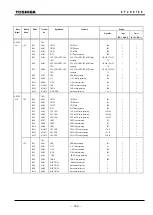
a-1 b-2
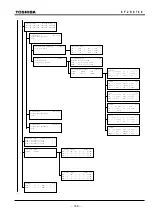
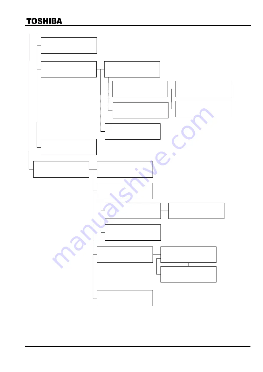
/3 Binary output (IO#2)
Select BO ( 1- 13)
Select No.= _
/2 Binary input 1=Norm 2=Inv 1/ 8
BISW 1 Mechanical trip1 1 _
BISW 2 Mechanical trip2 1
BISW 3 Mechanical trip3 1
/5 Logic gate type & delay timer 1/ 2
Logic 1=OR 2=AND 1 _
BOTD 0=Off 1=On 1
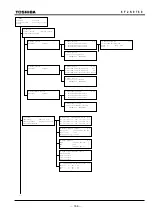
/2 LED 1/ 4
LED1 ( 0 - 3071): 21 _
LED2 ( 0 - 3071): 4
LED3 ( 0 - 3071): 67
/5 Input to logic gate 3/ 6
In #1 ( 0 - 3071): 21 _
In #2 ( 0 - 3071): 4
In #3 ( 0 - 3071): 67
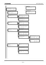
/2 Binary output
1=IO#2 2=IO#3
/4 Setting (BO 1 of IO#2)
1=Logic gate type & delay timer
2=Input to logic gate
/4 Setting (BO 12 of IO#2)
1=Logic gate type & delay timer
2=Input to logic gate
/3 Binary output (IO#3)
Select BO ( 1- 10)
Select No.= _
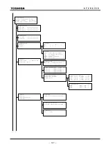
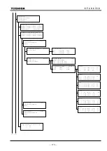
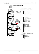
/1 Test
1=Switch 2=Binary output
3=Timer 4=Logic circuit
/2 Switch 1/ 3
A.M.F. 0=Off 1=On 1 _
Reset 0=Off 1=On 0
IECTST 0=Off 1=On 0
/2 Timer 1/ 1
Timer( 1 - 15): 1 _
/2 Binary output
1=IO#1 2=IO#2 3=IO#3
/3 BO (0=Disable 1=Enable) 1/ 5
IO#1 TP-1: TB4- A1, B1 1 _
IO#1 TP-2: TB4- A2, B2 1
IO#1 TP-3: TB4- B2, B3 1
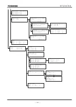
/3 BO
Keep pressing 1 to operate.
Press CANCEL to cancel.
/2 Timer
Press ENTER to operate.
Press CANCEL to cancel.
/2 Timer
Operating . . .
Press END to reset.
Press CANCEL to cancel.
/2 Logic circuit 1/ 2
TermA( 0 - 3071): 1 _
TermB( 0 - 3071): 48
/3 BO (0=Disable 1=Enable) 1/ 10
IO#3 BO1: TB2- A1, B1 1 _
IO#3 BO2: TB2- A2, B2 1
IO#3 BO3: TB2- A3, B3 1
Содержание GRT100 Series
Страница 55: ... 54 6 F 2 S 0 7 8 9 TRANSFORMER PROTECTION GRT100 Operation keys 101B 21 11 Figure 3 1 9 Front Panel ...
Страница 142: ... 141 6 F 2 S 0 7 8 9 Appendix A Block Diagram ...
Страница 144: ... 143 6 F 2 S 0 7 8 9 Appendix B Signal List ...
Страница 159: ... 158 6 F 2 S 0 7 8 9 ...
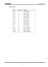
Страница 160: ... 159 6 F 2 S 0 7 8 9 Appendix C Variable Timer List ...
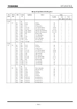
Страница 162: ... 161 6 F 2 S 0 7 8 9 Appendix D Binary Output Default Setting List ...
Страница 165: ... 164 6 F 2 S 0 7 8 9 ...
Страница 166: ... 165 6 F 2 S 0 7 8 9 Appendix E Details of Relay Menu and LCD and Button Operation ...
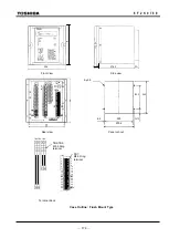
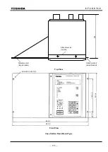
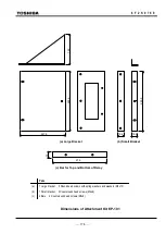
Страница 174: ... 173 6 F 2 S 0 7 8 9 Appendix F Case Outline Flush Mount Type Rack Mount Type ...
Страница 179: ... 178 6 F 2 S 0 7 8 9 ...
Страница 180: ... 179 6 F 2 S 0 7 8 9 Appendix G External Connections ...
Страница 185: ... 184 6 F 2 S 0 7 8 9 ...
Страница 200: ... 199 6 F 2 S 0 7 8 9 ...
Страница 201: ... 200 6 F 2 S 0 7 8 9 Appendix J Return Repair Form ...
Страница 205: ... 204 6 F 2 S 0 7 8 9 Customer Name Company Name Address Telephone No Facsimile No Signature ...
Страница 206: ... 205 6 F 2 S 0 7 8 9 ...
Страница 207: ... 206 6 F 2 S 0 7 8 9 Appendix K Technical Data ...
Страница 220: ... 219 6 F 2 S 0 7 8 9 ...
Страница 221: ... 220 6 F 2 S 0 7 8 9 Appendix M Symbols Used in Scheme Logic ...
Страница 224: ... 223 6 F 2 S 0 7 8 9 ...
Страница 225: ... 224 6 F 2 S 0 7 8 9 Appendix N Implementation of Thermal Model to IEC60255 8 ...
Страница 228: ... 227 6 F 2 S 0 7 8 9 ...
Страница 229: ... 228 6 F 2 S 0 7 8 9 Appendix O IEC60870 5 103 Interoperability and Troubleshooting ...
Страница 241: ... 240 6 F 2 S 0 7 8 9 Appendix P Modbus Interoperability ...
Страница 255: ... 254 6 F 2 S 0 7 8 9 ...
Страница 256: ... 255 6 F 2 S 0 7 8 9 Appendix Q Inverse Time Characteristics ...
Страница 259: ... 258 6 F 2 S 0 7 8 9 ...
Страница 260: ... 259 6 F 2 S 0 7 8 9 Appendix R Failed Module Tracing and Replacement ...
Страница 266: ... 265 6 F 2 S 0 7 8 9 Appendix S Ordering ...
Страница 269: ... 268 6 F 2 S 0 7 8 9 3 1 Oct 2 2017 Republished under spin off company ...
Страница 270: ......