


126
6
F
2
S
0
7
8
9
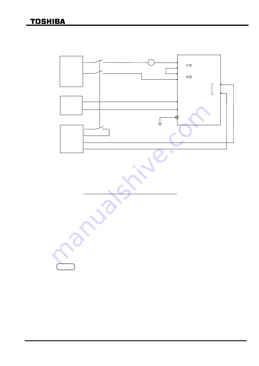
6.5.1.7 Inverse time overcurrent elements OCI, EFI
The testing circuit is shown in Figure 6.5.11.
Single-phase
current
source
A
TB 1
- 2
-1
- 7
- 8
I a
IN
GRT100
Monitoring
jack
A
0V
TB 4 - A16
- A17
E
DC
power
supply
Time
counter
Start
Stop
OV
Figure 6.5.11 Testing OCI and EFI (Model 100s, 200s)
One of the four inverse time characteristics can be set, and the output signal numbers are as
follows:
Element
Signal number
1OCI, 2OCI, 3OCI
50, 56, 62
1EFI, 2EFI, 3EFI
73, 76, 79
Fix the time characteristic to test by setting the OCI or EFI on the "OC" screen.
"Setting (change)" sub-menu
"Protection" screen
"Trip" screen
"Protection element"
screen
"OC" screen
The testing procedure is as follows:
Press 4 (= Logic circuit) on the "Test" sub-menu screen to display the "Logic circuit" screen.
Enter a signal number to observe the OCI or EFI output at monitoring jack A and press the
ENTER
key.
Apply a test current and measure the operating time. The magnitude of the test current should
be between 1.2
I
s
to 20
I
s
, where I
s
= (CT secondary rated current) × (OCI or EFI current
setting).
Calculate the theoretical operating time using the characteristic equations shown in Section
2.11.4. Check that the measured operating time is within the error mentioned below.
Accuracy: Standard, Very and Long-time inverse: IEC 60255-3 class 5
Extremely inverse: IEC 60255-3 class 7.5
Содержание GRT100 Series
Страница 55: ... 54 6 F 2 S 0 7 8 9 TRANSFORMER PROTECTION GRT100 Operation keys 101B 21 11 Figure 3 1 9 Front Panel ...
Страница 142: ... 141 6 F 2 S 0 7 8 9 Appendix A Block Diagram ...
Страница 144: ... 143 6 F 2 S 0 7 8 9 Appendix B Signal List ...
Страница 159: ... 158 6 F 2 S 0 7 8 9 ...
Страница 160: ... 159 6 F 2 S 0 7 8 9 Appendix C Variable Timer List ...
Страница 162: ... 161 6 F 2 S 0 7 8 9 Appendix D Binary Output Default Setting List ...
Страница 165: ... 164 6 F 2 S 0 7 8 9 ...
Страница 166: ... 165 6 F 2 S 0 7 8 9 Appendix E Details of Relay Menu and LCD and Button Operation ...
Страница 174: ... 173 6 F 2 S 0 7 8 9 Appendix F Case Outline Flush Mount Type Rack Mount Type ...
Страница 179: ... 178 6 F 2 S 0 7 8 9 ...
Страница 180: ... 179 6 F 2 S 0 7 8 9 Appendix G External Connections ...
Страница 185: ... 184 6 F 2 S 0 7 8 9 ...
Страница 200: ... 199 6 F 2 S 0 7 8 9 ...
Страница 201: ... 200 6 F 2 S 0 7 8 9 Appendix J Return Repair Form ...
Страница 205: ... 204 6 F 2 S 0 7 8 9 Customer Name Company Name Address Telephone No Facsimile No Signature ...
Страница 206: ... 205 6 F 2 S 0 7 8 9 ...
Страница 207: ... 206 6 F 2 S 0 7 8 9 Appendix K Technical Data ...
Страница 220: ... 219 6 F 2 S 0 7 8 9 ...
Страница 221: ... 220 6 F 2 S 0 7 8 9 Appendix M Symbols Used in Scheme Logic ...
Страница 224: ... 223 6 F 2 S 0 7 8 9 ...
Страница 225: ... 224 6 F 2 S 0 7 8 9 Appendix N Implementation of Thermal Model to IEC60255 8 ...
Страница 228: ... 227 6 F 2 S 0 7 8 9 ...
Страница 229: ... 228 6 F 2 S 0 7 8 9 Appendix O IEC60870 5 103 Interoperability and Troubleshooting ...
Страница 241: ... 240 6 F 2 S 0 7 8 9 Appendix P Modbus Interoperability ...
Страница 255: ... 254 6 F 2 S 0 7 8 9 ...
Страница 256: ... 255 6 F 2 S 0 7 8 9 Appendix Q Inverse Time Characteristics ...
Страница 259: ... 258 6 F 2 S 0 7 8 9 ...
Страница 260: ... 259 6 F 2 S 0 7 8 9 Appendix R Failed Module Tracing and Replacement ...
Страница 266: ... 265 6 F 2 S 0 7 8 9 Appendix S Ordering ...
Страница 269: ... 268 6 F 2 S 0 7 8 9 3 1 Oct 2 2017 Republished under spin off company ...
Страница 270: ......