background image

6-3-9. Procedure to Update the Firmware 

Devices to use 

- Dedicated power supply (accessory) 
- SD card 

For firmware writing 

       
Notes 

- There are two procedures to update the firmware.  If the Procedure 1 would not work successfully, try the 

Procedure 2 to update the firmware. 

- Toshiba provides the latest firmware as soon as the version is updated.  It is recommended to always use 

the latest version. 

- "GSCR20.bin" is only the file provided with the firmware version renewal.  The "UP_R20.bin" is an auxiliary 

firmware used for writing "GSCR20.bin" in under the Procedure 2.  It is recommended to use the same file. 

- When the power is shut down accidentally during the update, the system may not start even after rebooting 

the power.  In that case, it is necessary to update the firmware with following the Procedure 2. 


Procedure 1 

1) Write the firmware for update (file name: GSCR20.bin) to the root directory of SD card. 
2) Connect the AC adapter and insert the SD card to the camera. 
3) Turn on the camera. 
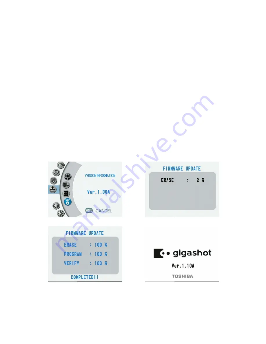
4) Press the MENU button and select "SETUP" -> "SYSTEM" -> "VERSION INFORMATION" from either the 

recording menu or the playback menu.  The version information should be displayed on the monitor. (Fig. 
6.3.9.1). 

4) The screen shown in Fig. 6.3.9.2 will be displayed by holding the movie REC button for several seconds.  

Then, the update will start. 

5) The update is completed when the message "COMPLETED" is displayed on the monitor screen (Fig. 

6.3.9.3). Then, turn the power off.  

6) Turn on the power again and confirm if the version information on the title screen is updated (Fig. 6.3.9.4). 


Fig. 6.3.9.1 

Fig. 6.3.9.2 


Fig. 6.3.9.3 

Fig. 6.3.9.4 


50 

Содержание Gigashot GSC-R30

Страница 1: ...SERVICE MANUAL HARD DISK CAMERA FILE NO 400 200604GR GSC R60 GSC R30 CREATED IN JAPAN March 2006 S ...

Страница 2: ...ement of parts is not only confined to manufacture The same green parts used in manufacture must also be used as replacement parts 2 LEAD FREE SOLDER This product is manufactured using lead free solder as a part of a movement within the consumer products industry at large to be environmentally responsible Lead free solder must be used in the servicing and repair of this product WARNING This produc...

Страница 3: ...layback Mode Movie 23 3 3 6 Playback Mode Still Image 23 3 3 7 USB Communication 23 3 3 8 LAN Communication 24 3 3 9 Flash Operation 24 3 3 10 Battery Charge Operation 24 3 3 11 Irregular Mode Detect Line 24 4 Troubleshooting 25 5 Disassembly Assembly 27 5 1 Disassembly 27 5 2 Assembly 34 6 Adjustment 41 6 1 Items to adjust 41 6 2 Devise to Use 41 6 3 Adjustment Procedure 42 6 3 1 CCD2CH Adjustmen...

Страница 4: ...el change at playback Lens 10x optical zoom Auxiliary light 2 LED lamps Flash Grip belt Backlight adjustment button Auxiliary light button STATUS LED MEDIA LED Terminal cover DC IN 10V terminal A V OUT terminal Video REC button Jog dial OK button MENU button LCD monitor POWER switch SD slot Mode LED Mode lever 3 ...

Страница 5: ...3 Time remained for video shooting 4 Indicator still images 5 Number of still images can be taken 6 Zoom bar 7 Focus 8 Scene 9 Flash 10 Exposure adjustment 11 Self timer 12 White balance 13 ISO sensitivity 14 Photometry mode 15 Camera shake adjustment 16 Video quality 17 Wind noise reduction 18 Still image size 19 Still image quality 20 Continuous shooting 21 Media 22 Album 23 Date and time 24 Foc...

Страница 6: ...rations Focus setting Video REC start Zoom MENU Zoom Video REC OK up OK Right Press OK OK left Still REC Half push OK down Flash setting Exposure bias setting AF AE lock OSD details display Recording menu Scene setting 5 ...

Страница 7: ...er to the playback side 1 4 6 5 9 2 7 8 11 2 4 5 6 12 10 3 Video 1 7 8 3 Still image 12 1 Playback mode 2 Battery level gauge 3 Recoding date and time 4 Drive 5 Album 6 File number 7 Previous image 8 Next image 9 Playback mode 10 Video icon 11 Video record time 12 Guide 6 ...

Страница 8: ...on T T Press OK Press OK OK up OK left or JOG left OK right or JOG right Display previous image Display next image Video playback Information display OK down OK down W W Thumbnail display W W MENU MENU Video playback method Rotation display Play menu Album display Drive display 7 ...

Страница 9: ...ith zooming MENU T W for zooming Stop One touch replay 1 20 One touch skip 1 20 Toggle for OSD display no OSD display RIGHT EXP MODE R MODE P M REC H SHUTTER F SHUTTER T W MENU UP FOCUS DOWN SCENE LEFT FLASH OK JOG L JOG R To photography mode Rewinding 3x F Forward 3x Playback Pause F Forward 3x F Forward 15x Pause Playback Rewinding 3x Rewinding 15x Frame rewind Frame playback Playback F Forward ...

Страница 10: ...he connection adapter to the camera Turn on the power while PC is connected to the connection adapter When PC is connected under the USB mode the indication of either HIGH SPEED MODE or FULL SPEED MODE will be displayed on the LCD monitor Since the camera is in the protection state during the FULL SPEED connection writing from PC to the camera will be prohibited The arrow direction changes as well...

Страница 11: ...he AC adapter to the cradle then connect the cradle via a LAN cable to the RD that has Dubbing through network function The LAN mode becomes available by pressing the LAN button on the cradle Connection completed Press OK 10 ...

Страница 12: ...2 Mechanical Parts 2 1 Explode Diagram GSC R60 11 ...

Страница 13: ...GSC R30 12 ...

Страница 14: ...00462420 GSC R60 P000462300 GSC R30 AA06 Top Cover ASSY 1 P000461930 AA11 Lens Cover ASSY 1 P000461940 AA08 Back Cover ASSY 1 P000461950 AA05 Zoom Cover ASSY 1 P000461960 AA14 Sensor Cover ASSY 1 P000461970 Mechanical Parts 2 2 Camera Part List 1 Left Cover ASSY AA02 Photo 13 ...

Страница 15: ... A110 Screw Cap 1 P000461990 A306 Lens Cushion 4 P000462000 P000462450 GSC R60 P000462330 GSC R30 A706 SN Label 1 P000462010 P000462430 GSC R30 P000462310 GSC R30 for GSC R60 4 P000462440 for GSC R30 2 P000462320 A358 Protection Gel A316 Protection Rubber 2 A703 Rating Label 1 14 ...

Страница 16: ...462020 A355 Shield Gasket A 1 P000462030 A356 Shield Gasket B 1 P000462040 AC15 HDD Case ASSY 1 Not Service Part AC40 HDD Cover ASSY 1 Not Service Part A305 Lens Holder 1 Not Service Part AC12 Flash Plate ASSY 1 Not Service Part A152 Microphone Plate 1 Not Service Part 15 ...

Страница 17: ...vice Part A346 Thermal Sheet A 1 Not Service Part A347 Thermal Sheet B 2 Not Service Part A349 EMI Sheet A 1 Not Service Part A350 EMI Sheet B 1 Not Service Part A351 EMI Sheet C 1 Not Service Part A900 Screw Kit 1 P000462050 HA52 Lens Module ASSY 1 P000462060 Module 16 ...

Страница 18: ...070 P000462460 GSC R30 P000462340 GSC R30 HA56 Microphone ASSY 1 P000462080 HA55 Speaker ASSY 1 P000462090 W999 FLASH MAIN FPC 1 P000462170 U001 MAIN PCB ASSY 1 P000462100 UA51 FLASH PCB ASSY 1 P000462110 UA02 JACK PCB ASSY 1 P000462120 PCB Assembly HA5A HDD ASSY 1 17 ...

Страница 19: ...Part Cord Part Name Qty Purchase Code Photo U006 SENSOR PCB ASSY 1 P000462130 UA11 TERMINAL PCB ASSY 1 P000462140 U008 3 WAY FPC ASSY 1 P000462150 UA09 LENS MAIN FPC ASSY 1 P000462160 18 ...

Страница 20: ...3 MAIN PCB ASSY U001 Main Cover ASSY AA01 1 MAIN PCB ASSY U001 Battery Case ASSY AC11 3 4 A327 M1 7x3 0 M 3 0 5 Ni Silver TERMINAL PCB ASSY UA11 Main Cover ASSY AA01 2 2 5 A330 M1 7x3 5 M 3 0 5 Ni Silver Lens Cover ASSY AA11 Flash Plate ASSY AC12 1 1 6 A328 M1 7x4 0 M 3 0 5 Ni Silver Left Cover ASSY AA02 HDD Case ASSY AC15 2 5 Left Cover ASSY AA02 Flash Plate ASSY AC12 1 LCD Plate A313 LCD ASSY HA...

Страница 21: ...2 3 8 A V LAN MN52B8 STCLK 27MHz 4 GIO PWM BAT3V LC15009 USB USB WKP0 ACCERA CLK72 LH28F640BFB PTTL80 Sip 1280 ALR267FGX SANYO BIU Audio Codec MIC L R Audio ROM AST API APDN ACLK4M ML2201 SOUND SP BATT LID JOGS W MENU S W ARROWKEY MODE S W BATCVR STXTON YSIG2 CSIG2 VBS2 Y C VBS DC2 ZVR U3V 4 SDDAT 3 0 WM8978 MN31121SA VSP2254GSJR DB 13 0 1 4 1 4 AFED 11 0 1 2 72MHz CLK36 CLK72 HALL Circuit IRHO IR...

Страница 22: ...z 25MHz 48MHz and 72MHz It also performs a horizontal synchronization between the CCD system and the VIDEO system DSP It conducts image signal processing USB communication control SD card control ATA communication control JPEG control VIDEO digital signal control VIDEO analog output control etc It controls overall system by a built in CPU SDRAM for DSP operation A memory for DSP operation It is co...

Страница 23: ...ash unit FPC_FRONT FPC_FRONT consists of TARRY lamp and IR sensor and is connected to the PCB_MAIN It receives the information of TARRY lamp and sends out an IR sensor signal FPC_HDD A flexible tube that connects the 1 8 inch HDD to the PCB_MAIN FPC_LCD A flexible tube that connects the PCB_MAIN to the 2 5 inch LCD monitor It also contains open close up down switch of LCD wing FPC_STROBE A flexibl...

Страница 24: ...Resetting of CPU on DSP will be deactivated when the reset deactivation voltage is applied to the reset IC on the MAIN board and the CPU starts its operation 3 3 2 Power Off Operation When DSP sends the command to turn off the power the sub microcomputer turns the switch LOW for each voltage 1 5V 1 2V 5V 2 5V 3 3V etc and the power supply circuit stops supplying power to the MAIN board The power s...

Страница 25: ...e becomes too high or too low the charge abort signal will be sent to the battery charge IC Then the IC will stop charging the battery 3 3 11 Irregular Mode Detect Line The following shows the description for electrical surge detection on the POWER board and the lines related to the battery detection DET33V line It monitors the disconnection of the power cable It turns to LOW when neither the AC a...

Страница 26: ...it in LCD back light system Fuse F7001 disconnected Short circuit in cradle 10V system Fuse F6501 disconnected Short circuit in JACK board 10V system 2 Not operational by battery MAIN board defect Replace MAIN PCB ASSY U001 MAIN board defect Replace MAIN PCB ASSY U001 Cradle defect Replace cradle Y540 Wiring defect in hinge Replace LCD HA54 MAIN board defect Replace MAIN PCB ASSY U001 FPC HEAD def...

Страница 27: ...d defect Replace MAIN PCB ASSY U001 MAIN board defect Replace MAIN PCB ASSY U001 JACK board defect Replace JACK PCB ASSY UA02 Cradle defect Replace Cradle YR01 MAIN board defect Replace MAIN PCB ASSY U001 JACK board defect Replace JACK PCB ASSY UA02 Cradle defect Replace Cradle YR01 MAIN board defect Replace MAIN PCB ASSY U001 Cradle defect Replace Cradle YR01 Replace HDD ASSY HA5A Replace MAIN PC...

Страница 28: ...equest of a purport needed without erasing the picture in HDD from a user in case HDD s is exchanged When you cannot perform reading of data utilize commercial file restoration software Check the repaired camera arrives to a user before deleting the backup data immediately 5 1 Disassembly 5 Disassembly Assembly Do not formatting the hard disk drive carelessly Do not deleting the Image and other fi...

Страница 29: ...s of the portion near a connector it removes with tweezers 10 An Electric discharge machine is applied between the elecrodes of the capacitor of the FLASH PCB ASSY UA51 and it discharges Discharge certainly for electric shock prevention When you discharge be careful for the terminal of an electric discharge machine not to contact other parts lens cover etc 11 Remove the screws A332 2 and take off ...

Страница 30: ...6 The connector of 3 WAY FPC ASSY U008 connected to the MAIN PCB ASSY U001 and the JACK PCB ASSY U002 is removed 17 Remove the screw A324 18 The connector of Microphone ASSY HA56 remove to the JACK PCB ASSY UA02 and Top Cover ASSY AA06 is raised and removed from a flash side Top Cover ASSY AA06 has lug LCD side it lift up and remove from a flash side 19 Detach the Top Cover ASSY AA06 and the conne...

Страница 31: ...sary when not exchanging the Main Cover ASSY AA01 and the Speaker ASSY HA55 22 Remove the lead wire of JACK PCB ASSY UA02 from the connector of MAIN PCB ASSY U001 23 Remove the screws A324 2 and take off the JACK PCB ASSY UA02 This work is unnecessary when not exchanging the JACK PCB ASSY UA02 24 Remove the screws A330 and A331 25 Pushing the Lug with tweezers and remove the Main Cover ASSY AA01 2...

Страница 32: ...f MAIN PCB ASSY U001 connected is removed 31 Lens Module ASSY HA52 Lens Holder A305 Lens Cushions A306 4 and LENS MAIN FPC ASSY UA09 detach from Lens Block This work is unnecessary when not exchanging Lens Module ASSY HA52 LENS MAIN FPC ASSY UA09 and Lens Cushions A306 4 Since it is easy to separate from a Lens Cushions A306 Be careful not to lose 32 Remove the Shield Gasket A A335 and Shield Gask...

Страница 33: ...screws A326 2 Remove the EMI Sheet A A349 and EMI Sheet B A350 37 Remove the screws A326 2 Remove the SENSOR PCB ASSY U006 of FPC from the connector 38 Raise the MAIN PCB ASSY U001 and remove the connector as shown Remove the MAIN PCB ASSY EMI Sheet C A351 is separate at this time be careful not to lose 39 Detach the MAIN PCB ASSY U001 and FLASH MAIN FPC W999 This work is unnecessary when not exch...

Страница 34: ...SY U006 42 Remove the Thermal Sheet A A346 from the Battery Case ASSY AC11 This work is unnecessary when not exchanging the Battery Case ASSY AC11 43 Remove the Sensor Cover ASSY AA14 from Main Cover ASSY AA01 This work is unnecessary when not exchanging the Sensor Cover ASSY AA14 and Main Cover ASSY AA01 44 Remove the screws A328 2 and detach the Main Cover ASSY AA01 LCD ASSY HA54 and LCD Plate A...

Страница 35: ...uck on Battery Case ASSY AC11 When the lead wire of a Battery Case ASSY AC11 is long it bundles to about 5cm and stops with the tape 4 Use the screw A331 and connect the SENSOR PCB ASSY U006 to Battery Case ASSY AC11 5 Use the screws A332 4 and A325 and connect the Battery Case ASSY AC11 to Main Cover ASSY AA01 A screw A325 use near the tripod screw 6 Install the FLASH MAIN FPC W999 to MAIN PCB AS...

Страница 36: ...Y AC11 is not to insert check the position of lead wire 10 Use the screws A326 2 and fix MAIN PCB ASSY U001 and connect the FPC from SENSOR PCB ASSY U006 Before stopping a screw a position is united with tweezers so that the hole and screw hole of the EMI Sheet C A351 may suit 11 Use the Screw A326 and install the EMI Sheet B A350 12 EMI Sheet A A349 joints to a Main Cover ASSY AA01 and it fixes w...

Страница 37: ...ASSY UA11 in order of Shield Gasket B A356 and Shield Gasket A A355 18 Connect the LENS MAIN FPC ASSY UA09 to Lens Module ASSY HA52 and install the Lens Cushion A306 4 and Lens Holder A305 The connector of FPC is an upper point of contact 19 Tapes are stuck as shown Do not stick on the moving part of connector 20 The position of a Lens Cushion A306 is united and a lens block is set to Main Cover A...

Страница 38: ...eet two sheets is stuck on the Flash Plate ASSY AC12 Don t insert the wire of a FLASH PCB ASSY UA51 24 Install the JACK PCB ASSY U002 to the Flash Plate ASSY AC12 with screw A324 2 25 Install the Microphone Plate A152 with the screw A331 26 Install the FLASH PCB ASSY UA51 and JACK PCB ASSY UA02 to the Flash Plate ASSY AC12 and set the Main Cover ASSY AA01 with the screw A326 as shown Be careful to...

Страница 39: ...k on a Main Cover ASSY AA01 and connect a lead wire to the connector of a JACK PCB ASSY UA02 31 Stuck on the Speaker Cushion A320 the lead wire of a Speaker ASSY HA55 is fixed to a Microphone Plate A152 with a tape 32 Attached the Microphone ASSY HA56 to the TOP Cover ASSY AA06 and set the TOP Cover ASSY with a screw A324 Suit a Top Cover ASSY to the Lug of LCD side 33 Connect the lead wire of the...

Страница 40: ... ASSY AC15 is set and the EMI Sheet B A350 and the EMI sheet C A351 are fixed to Main Cover ASSY AA01 with screws A332 2 Unite correctly the position of the EMI Sheet B A350 and the EMI Sheet C A351 40 FPC from a Zoom Cover ASSY AA05 is inserted in the connector of a FLASH PCB ASSY UA51 and it connect Install the Zoom Cover ASSY AA05 with screws A326 2 Suit the lug of Zoom Cover ASSY AA05 to Flash...

Страница 41: ...ase ASSY AC15 44 When a Left Cover ASSY AA02 is exchanged new SN Label A706 is stuck on a Left Cover ASSY and S N is filled in 45 Install the Left Cover ASSY AA02 with screws A328 2 and A326 A screw A326 use the bottom 46 Open the terminal cover and insert the screws A328 and A332 The screw A328 use to right side of terminal cover The screw A332 use to left side of terminal cover 47 Stuck on the S...

Страница 42: ...y not be given unless specified order is followed 2 Update the firmware only when the versions is different 3 All items will be reset to the default values when the factory setting is applied 4 The contents of HDD will not be erased by the adjustment 6 2 Devise to Use Standard light source Model name LSB 6M 10 Manufacturer Tsubosaka Electric Co Ltd For CCD2CH adjustment and white balance purpose C...

Страница 43: ...g 6 3 1 1 4 Turn on the camera with holding the MENU button 5 The adjustment menu shown in Fig 6 3 1 2 will be displayed on the LCD monitor Select CCD 2CH by rotating the JOG dial or by pushing up down the OK button and press the OK button down to right to proceed 6 The image shown in Fig 6 3 1 3 will be displayed on the LCD monitor Press the OK button to proceed 7 After the automatic adjustment t...

Страница 44: ...camera with holding the MENU button 5 The adjustment menu shown in Fig 6 3 1 2 will be displayed on the LCD monitor Select SENSITIVE by rotating the JOG dial or by pushing up down the OK button and press the OK button down to right to proceed 6 The image shown in Fig 6 3 2 2 will be displayed on the LCD monitor Press the OK button to proceed 7 After the automatic adjustment the result will be disp...

Страница 45: ...ith holding the MENU button 5 The adjustment menu shown in Fig 6 3 3 1 will be displayed on the LCD monitor Select IRIS ND by rotating the JOG dial or by pushing up down the OK button and press the OK button down to right to proceed 6 The image shown in Fig 6 3 3 2 will be displayed on the LCD monitor Press the OK button to proceed 7 After the automatic adjustment the result will be displayed at t...

Страница 46: ...ith holding the MENU button 5 The adjustment menu shown in Fig 6 3 4 1 will be displayed on the LCD monitor Select SHUTTER by rotating the JOG dial or by pushing up down the OK button and press the OK button down to right to proceed 6 The image shown in Fig 6 3 4 2 will be displayed on the LCD monitor Press the OK button to proceed 7 After the automatic adjustment the result will be displayed at t...

Страница 47: ...ect DEFECT PIXEL by rotating the JOG dial or by pushing up down the OK button and press the OK button down to right to proceed 6 The image shown in Fig 6 3 5 2 will be displayed on the LCD monitor Press the OK button to proceed 7 After the automatic adjustment the result will be displayed at the bottom of monitor screen within several seconds As shown in Fig 6 3 5 3 the adjustment is completed whe...

Страница 48: ... with holding the MENU button 5 The adjustment menu shown in Fig 6 3 6 1 will be displayed on the LCD monitor Select W BALANCE by rotating the JOG dial or by pushing up down the OK button and press the OK button down to right to proceed 6 The image shown in Fig 6 3 6 2 will be displayed on the LCD monitor Press the OK button to proceed 7 After the automatic adjustment the result will be displayed ...

Страница 49: ...be displayed on the LCD monitor Select ZOOM FOCUS by rotating the JOG dial or by pushing up down the OK button and press the OK button down to right to proceed 5 The image shown in Fig 6 3 7 2 will be displayed on the LCD monitor Adjust the camera position to make the cross on the screen overlapping with the center of the chart 6 Press the OK button to proceed 7 After the automatic adjustment the ...

Страница 50: ...ENU button and select SETUP SYSTEM FORMAT HDD from either the recording menu or the playback menu and then press the OK button to proceed Fig 6 3 8 1 4 The confirmation screen will be displayed Fig 6 3 8 2 Select YES and press the OK button to proceed 5 It returns to the setup screen after the formatting is completed Then turn off the camera Fig 6 3 8 1 Fig 6 3 8 2 49 ...

Страница 51: ...ooting the power In that case it is necessary to update the firmware with following the Procedure 2 Procedure 1 1 Write the firmware for update file name GSCR20 bin to the root directory of SD card 2 Connect the AC adapter and insert the SD card to the camera 3 Turn on the camera 4 Press the MENU button and select SETUP SYSTEM VERSION INFORMATION from either the recording menu or the playback menu...

Страница 52: ... the camera with holding the movie REC button 4 The screen showing in Fig 6 3 9 5 will be displayed and then the update will start 5 The update is completed when the message Update completed is displayed on the monitor screen Fig 6 3 9 6 Then turn off the power 6 Turn on the power again and confirm that the version information on the title screen is updated Fig 6 3 9 5 Fig 6 3 9 6 51 ...

Страница 53: ...ng destination and default configuration If there is any image stored in HDD a warning message HDD is not formatted will be displayed at the bottom of the monitor This is not an error Table 6 3 10 1 Region code Destination OSD language Video output Date format A North America ENGLISH NTSC MM DD YYYY J Japan Japanese NTSC YYYY MM DD 7 When a warning message Model Name is not correct is displayed at...

Страница 54: ...7 Packing Parts 7 1 Packing Explode Diagram Y906 Y919 Y920 Y922 Y923 Y921 Y942 Y903 Y931 Y928 Y940 Y925 Y926 Y941 Y927 Y930 Y721 Y721 Y707 YR01 Y905 Y907 YBT2 YBT1 Y902 Y901 Y904 53 ...

Страница 55: ... Only 100 120V YBT1 Lithium Ion Battery 1 Not Service Part YBT2 Coin Battery CR2025 1 Not Service Part Y907 Lens Cap ASSY 1 P000462210 Y905 IR Remote Controller 1 P000462220 YR01 Cradle 1 P000462480 Only with GSC R60 Y707 Gift Box 1 Not Service Part Y721 Packing 1 Not Service Part Y926 Warranty U S A E 1 Not Service Part Y941 Warranty U S A S 1 Not Service Part Y927 Warranty Canada E 1 Not Service...

Страница 56: ...0 V terminal Power supply Dedicated rechargeable lithium ion battery AC adapter SQPH20W10P 02 Recording media Hard disk drive 60GB 2 GSC R60 or 30GB 2 GSC R30 SD Memory Cards 128MB 256MB 512MB 1GB or 2GB supported Videos Recording format MPEG 2 PS Recorded pixels 720 480 LP 352 480 Audio Dolby Digital 48kHz 16 bit stereo 192 384kbps Still images Recording format JPEG Exif 2 21 DCF 1 0 compliant Re...

Страница 57: ...900 Screw Kit 1 P000462050 HA52 Lens Module ASSY 1 P000462060 HA54 LCD ASSY 1 P000462070 HA5A HDD ASSY 1 P000462460 for GSC R60 P000462340 for GSC R30 HA56 Microphone ASSY 1 P000462080 HA55 Speaker ASSY 1 P000462090 W999 FLASH MAIN FPC 1 P000462170 U001 MAIN PCB ASSY 1 P000462100 UA51 FLASH PCB ASSY 1 P000462110 UA02 JACK PCB ASSY 1 P000462120 U006 SENSOR PCB ASSY 1 P000462130 UA11 TERMINAL PCB AS...

Страница 58: ...GSC R60 GSC R30 ...

Отзывы: