1600/2000/2500 IMAGE PROCESSING
6 - 2
December 2000 © TOSHIBA TEC
6.2 Image Processing Circuit
(1) Outline
This digital copier scans optically the original placed on the original glass and reads an original image
using the CCD (charge coupled device), and converts the image into electrical signals. The electrical
signals are A/D converted into digital signals and output from the CCD board as image signals. The
image signals from the CCD board are input to the image processing section where shading correc-
tion (compensation for variance in the CCD or the light source) and various image-processing opera-
tions are performed. The results are output to the printer.
(2) Image Processing Circuit on the SLG Board
The SLG board contains an image processing ASIC which implements the following functions.
<Functions>
High quality image processing, image memory editing, editing processing, gamma correction pro-
cessing, tone processing and external output system interface
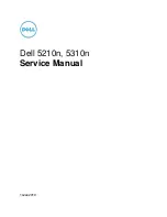
Fig. 6-2-1
07002
CCD board
CCD
A/D conversion
SLG board
Image processing
section
Shading correction
High quality image processing,
image memory editing, editing
processing, gamma correction,
tone processing, and external
output systems interface.
MAIN board
Laser unit
Laser drive
: Image data flow
External input systems interface
Image area control
Laser related control
ASIC [ST.LOUIS]
ASIC [PTC]
Smoothing processing
ASIC [EET]
Page memory
Memory copy, vertical/horizontal
alternate copy, sort copy, group
copy, magazine copy, simplex
reduction concatenation, duplex
reduction concatenation, image
combination, date annotation,
sheet insertion mode, etc.
Содержание DP1600
Страница 1: ...DIGITALPLAINPAPERCOPIER DP1600 2000 2500 File No 31100011 R0111216600 TTEC ...
Страница 2: ...Copyright 2000 TOSHIBA TEC CORPORATION ...
Страница 21: ...1600 2000 2500 OUTLINE OF THE MACHINE 2 8 December 2000 TOSHIBA TEC B 2 Switches SW2 SW1 02 02 04 ...
Страница 23: ...1600 2000 2500 OUTLINE OF THE MACHINE 2 10 December 2000 TOSHIBA TEC C 1 Motors M1 M3 M5 M7 M6 M4 M2 02 02 06 ...
Страница 145: ...8 PRINTING 8 1 8 1 General Description 8 1 8 2 Structure 8 2 8 3 Laser Diode 8 6 8 4 Disassembly and Replacement 8 7 ...
Страница 231: ...December 2000 TOSHIBA TEC 16 1 1600 2000 2500 PC BOARD 16 BOARD ASSEMBLY 16 1 PWA F MAN 16 01 01 ...
Страница 232: ...1600 2000 2500 PCB BOARD 16 2 December 2000 TOSHIBA TEC 16 2 PWA F RLY 16 02 01 ...
Страница 233: ...December 2000 TOSHIBA TEC 16 3 1600 2000 2500 PC BOARD 16 3 PWA F PIF 16 03 01 ...
Страница 234: ...1600 2000 2500 PCB BOARD 16 4 December 2000 TOSHIBA TEC 16 4 PWA F PNL 16 5 PWA F VR 16 04 01 16 05 01 ...
Страница 236: ...1600 2000 2500 PCB BOARD 16 6 December 2000 TOSHIBA TEC 16 7 PWA F FUS ASD AUD CND TWD SAD models 16 07 01 ...
Страница 237: ...17 WIRE HARNESS CONNECTION DIAGRAMS 17 1 ...
Страница 264: ...1 1 KANDA NISHIKI CHO CHIYODA KU TOKYO 101 8842 JAPAN ...