background image

8. OPERATION PANEL 


8- 11 


8. Beep 

Volume 

A volume of the buzzer that sounds in the event of an error or a warning is specified. 
There is a choice of 4 options: “Off,” “Min,” “Mid,” and “Max.” 
(“Intermediate” is selected as default.) 
 

9. Beep 

Pattern 

A time period during which the buzzer sounds in the event of an error or a warning is specified. 
There is a choice of 3 options: “10” (seconds), “60” (seconds), and “Cont.” 
(“10” (seconds) is selected as default.) 
 

10. LCD Contrast 

The contrast of the LCD is specified.    It can be adjusted in 5 levels while the actual contrast is 
being checked. 
(The intermediate contrast level is selected as default.) 
 

11. Language 

A language in which messages are shown on the LCD is selected. 
There is a choice of 2 options: “Japanese” and “English”. 
(“English” is selected as default.) 
 

12. Counter Reset 

The print count displayed on the Operation Panel can be cleared by selecting “Counter Reset” 
and pressing the [Enter] key. 
 

Содержание B-SX600 SERIES

Страница 1: ...TOSHIBA Barcode Printer B SX600 SERIES Owner s Manual ...

Страница 2: ... to provide reasonable rotection against harmful interference when the equipment is operated in a commercial environment This equipment generates uses and can radiate radio frequency energy and if not installed and sed in accordance with the instruction manual may cause harmful interference to radio communications Operations of this equipment in a residential area is likely to cause harmful interf...

Страница 3: ... wet hands as this may cause electric shock If the machines share the same outlet with any other electrical appliances that consume large amounts of power the voltage will fluctuate widely each time these appliances operate Be sure to provide an exclusive outlet for the machine as this may cause fire or electric shock Do not place metal objects or water filled containers such as flower vases flowe...

Страница 4: ...ty dust or gas Ensure the printer is operated on a level surface Any data stored in the memory of the printer could be lost during a printer fault Try to avoid using this equipment on the same power supply as high voltage equipment or equipment likely to cause mains interference Unplug the machine whenever you are working inside it or cleaning it Keep your work environment static free Do not place...

Страница 5: ...RINTER SETUP 2 1 2 1 Removing the Protective Materials 2 1 2 2 Installation Location 2 4 2 3 Connecting the Power Cord 2 5 2 4 Connecting the Printer with a USB interface to Your Computer 2 6 2 5 Connecting the Printer with a LAN interface to Your Computer 2 7 3 MEDIA AND RIBBON 3 1 3 1 Supply Specifications 3 1 3 2 Die cut Label 3 2 3 3 Notched Media 3 3 3 4 Label with Black Marks 3 4 3 5 Guarant...

Страница 6: ... Print Test Pattern 9 1 10 REMOVING JAMMED MEDIA 10 1 10 1 Removing Jammed Media from the Cutter Unit 10 1 10 2 Removing Jammed Media from the Peel off Unit 10 2 11 DAILY MAINTENANCE 11 1 11 1 Cleaning the Media Sensor 11 2 11 2 Cleaning the Platen 11 3 11 3 Cleaning the Ribbon Separation Plate 11 4 11 4 Cleaning the Ribbon Guide Bar 11 4 11 5 Cleaning the Print Head 11 5 11 6 Cleaning the Peel of...

Страница 7: ... in whole or in part without prior written permission of TOSHIBA TEC 2 The contents of this manual may be changed without notification 3 Please refer to your local Authorised Service representative with regard to any queries you may have in this manual This is a Class A product In a domestic environment this product may cause radio interference in which case the user may be required to take adequa...

Страница 8: ...ter It should be read carefully to make full use of the capabilities of the printer and maximize its life Particularly please read Safety Summary before handling or maintaining the printer For most queries please refer to this manual and keep it safe for future reference Please contact your nearest authorised TOSHIBA TEC representative for further information concerning this manual ...

Страница 9: ...lied with the printer Should any of them be missing please contact your nearest authorised TOSHIBA TEC representative for assistance Ferrite core for the model with a LAN interface Reset pin for the model with a LAN interface Unpacking instructions Warranty sheet US only Cleaning cloth CD ROM Owner s Manual this document ...

Страница 10: ...ecked through the Supply Window 3 Front Cover Unlock Button Used to open the Front Cover 4 Side Cover Grip Used to open the Side Cover 5 Media Outlet Printed outputs are ejected through the Media Outlet 6 Front Cover Opened when the media is loaded or replaced 7 Power Switch Used to turn the printer on off 8 Operation Panel Please refer to Section 8 OPERATION PANEL for further information 7 2 4 6 ...

Страница 11: ... connect the printer to a PC with a USB cable 2 Ventilation Slot Lets trapped heat pass out of the printer 3 Expansion I O Interface Connector Used to interface with an external device 4 AC Power Inlet 5 Fanfold Paper Slot Allows fanfold paper to feed into the printer from the printer back 1 2 3 4 5 ...

Страница 12: ... connect the printer to a PC with a LAN cable 2 Ventilation Slot Lets trapped heat pass out of the printer 3 Expansion I O Interface Connector Used to interface with an external device 4 AC Power Inlet 5 Fanfold Paper Slot Allows fanfold paper to feed into the printer from the printer back 1 2 3 4 5 ...

Страница 13: ...drawn into the moving parts be sure to load the media once the printer has stopped moving completely 3 To avoid injury be careful not to trap your fingers while opening or closing the cover 1 3 4 Interior Lower unit 1 Media End Sensor 2 Media Holder 3 Media Roll Damper 4 Media Roll Guide 5 Media Guide 6 Reflective Media Sensor 7 Transmissive Media Edge Sensor 8 Platen 9 Transmissive Media Centre S...

Страница 14: ...OVERVIEW 1 7 Upper Unit 1 Upper Unit Handle 2 Upper Unit Unlock Lever 3 Ribbon Stopper 4 Ribbon Shaft Supply side 5 Ribbon Tensioner 6 Print Head Pressure Selection Lever 7 Ribbon Shaft Take up side 2 4 7 3 6 1 5 ...

Страница 15: ...play 2 Error LED Red 3 Data LED Green 4 Feed key 5 Menu key 6 Cancel key 7 Enter key 8 Arrow keys 9 Pause key 10 Power LED Green 11 Ready LED Green Please refer to Section 8 OPERATION PANEL for further information about the Operation Panel 1 2 11 10 8 3 9 4 5 7 6 ...

Страница 16: ...position is at the centre of a gap a notch or a black mark Easy feed mode In the Easy feed mode the cut position is approximately 1 mm from the leading edge of the label positioned behind the cutter Fixed length feed mode In the Fixed Length feed mode the media is cut at equal interval of media pitch specified in the printer driver A cutter is located inside the Media Outlet Cut position Media pit...

Страница 17: ... may affect the cutter quality and shorten the cutter life Do not cut any materials other than paper e g fabrics and films as this may cause a printer failure The cutter is a consumable The cutting edge wears out from an extended period of use causing the cutter to be blunt When replacing the cutter please contact your nearest authorised TOSHIBA TEC representative for assistance When the perforate...

Страница 18: ...it This section describes the model with the Peel off Unit 1 5 1 Part names Rubber Roller Black Pinch Roller White Peel off Sensor Media Holding Roller Front Cover Unlock button Front Cover Media Holding Roller Peel off Unit Peel off Sensor ...

Страница 19: ...n after the media is fed backward after a tear off Otherwise a media feed error may occur The Peel off Sensor may malfunction if it is subject to direct lighting of a three band fluorescent lamp If this happens decrease the illumination intensity of the fluorescent lamp or relocate the printer Do not use the edge of the Peel off Plate to tear off the media as this may cause injuries or a printer f...

Страница 20: ...njuries Precautions Do not plug in the Power Cord until the printer is set up completely 1 Hold the Side Cover Grip and open the Side Cover completely 2 Push up the Upper Unit Unlock Lever underneath the Upper Unit Handle to unlock the Upper Unit 3 Hold and lift the Upper Unit Handle until it is locked Upper Unit Unlock Lever Upper Unit Handle CAUTION Side Cover Grip ...

Страница 21: ...on Tensioner of the Upper Unit 5 Press the Front Cover Unlock button and open the Front Cover frontward 6 Lift the Media Holder Plate Remove the Print Head Protective Sheet 7 Push up the Upper Unit Unlock Lever to unlock the Upper Unit Print Head Protective Sheet Front Cover Unlock Button Front Cover Media Holder Plate ...

Страница 22: ... 8 Take your finger off the Upper Unit Unlock Lever Hold the Upper Unit Handle and push the Upper Unit downward until it is locked Ensure that the Upper Unit is locked completely 9 Close both the Front and the Side Covers ...

Страница 23: ...ations that have the following adverse conditions Failure to do this may cause injuries or printer failure Direct sunlight High temperatures and humidity or low temperatures and humidity Rapid temperature changes Direct cold air Excessive vibration Dust Gas Near magnetic or electromagnetic devices Near open flames or wet locations On an unstable desk or rack Precautions Ensure that an AC outlet is...

Страница 24: ...the easy plugging and unplugging of the Power Cord Do not place any obstacles around the AC outlet Make sure that the printer is connected to a clean source of AC power and that no other high voltage devices that may cause line noise interference are connected to the same mains Otherwise this may affect the operation of the printer 1 Make sure that the printer Power Switch is in the OFF position 2...

Страница 25: ...sed choose USB 2 0 compatible products Pay attention to the orientation of the connector when connecting the USB cable It is not guaranteed that the printer functions in combination with any other USB devices e g USB flash memory If a USB device is used together with the printer at the same time it may not be detected properly depending on the combination of a USB device and a computer in use In t...

Страница 26: ...he LAN Interface Connector at the back of the printer 3 Connect the other end of the LAN cable into a network device such as a hub Precautions Be sure to fit the supplied ferrite core to a LAN cable If a different ferrite core is fitted to the cable communications with the computer may become unstable Pay attention to the orientation of the connector when connecting the LAN cable Choose a LAN cabl...

Страница 27: ...6 2 mm Ribbon width 30 to 120 mm A ribbon must be at least 10 mm wider than the loaded media Ribbon roll direction Ink side faces outside Ribbon inner core diameter 25 4 mm to 26 4 mm End of ribbon Minimum of 200 mm long silver film is attached to the end of the ribbon Outside roll diameter 70 mm or less Ribbon length Approx 300 m or less 1 If the length of a label is long place the printer on a s...

Страница 28: ...e Transmissive Media Centre Sensor is used to detect a print position The Transmissive Media Centre Sensor is located at the centre of the label feed path 1 3 Part Names and Functions Precautions The Transmissive Media Edge Sensor must be placed so that it does not come into contact with the media Media feed direction Label pitch 5 to 1 000 mm Transmissive Media Edge Sensor Page start line 25 mm G...

Страница 29: ...l When notched media is loaded the Transmissive Paper Edge Sensor is used Precautions The Transmissive Paper Edge Sensor must be placed so that it does not come into contact with the media Media feed direction Page start line Notch 4 mm or over 2 to 13 mm Transmissive Paper Edge Sensor 15 to 120 mm ...

Страница 30: ... the backing paper for the position detection purpose as illustrated below When a label stock with black marks is loaded the Reflective Media Sensor is used Label pitch 10 to 1 000 mm Page start line 12 mm or over Reflective Media Sensor Located under the media Media feed direction 2 to 13 mm Black mark on the reverse side 15 to 120 mm ...

Страница 31: ... loaded ribbon may be torn or the print quality may be degraded 1 Die cut label 2 Notched media B A A B Media width A 2 mm or over B 1 5 mm if a notch pitch is 100 mm or less B 2 5 mm if a notch pitch is more than 100 mm B B A A Label width Media width Label length A 2 mm or over B 1 5 mm if a label length is 100 mm or less B 2 5 mm if a label length is more than 100 mm ...

Страница 32: ...elf life is expired When you purchase media and ribbons There are a wide variety of media or ribbons depending on what they are made of and how the front and back surfaces are treated Please use only TOSHIBA TEC approved or recommended media and ribbons in order to ensure the best print quality TOSHIBA TEC shall not be liable for any print failures or defects arising from the use of non approved m...

Страница 33: ...f printing were completed However the printer does not determine that printing is completed unless an entire page is completely fed In this situation there are two options for restarting printing 1 If Yes is selected for Reprint Error Page in the Menu of the printer printing will be restarted from the most recently printed page at the time of media end or ribbon end 2 If No is selected printing wi...

Страница 34: ...t Upper Unit Unlock Lever CAUTION Be careful not to touch the Print Head Element while loading the ribbon Failure to do this may cause missing dots by static electricity or other print quality problems 1 Do not touch any moving parts To reduce the risk of fingers jewellery clothing etc being drawn into the moving parts be sure to load the ribbon once the printer has stopped moving completely 2 The...

Страница 35: ...shaft 4 Fit a new ribbon onto the Ribbon Shaft Supply side Load the ribbon so that it unrolls from the back side Supplemental Remarks The ribbon can be placed on the Ribbon Shaft Supply side more easily by gently holding and squeezing the centre of the metal plate of the Ribbon Shaft Supply side Gently squeeze metal plate Metal plate Release button Ribbon Stopper Scale Ribbon Shaft Supply side ...

Страница 36: ...n Shaft Take up side more easily by gently holding and squeezing the centre of the metal plate of the Ribbon Shaft Take up side 6 Unroll and draw the ribbon under the Upper Unit and affix the leading edge of the ribbon self adhesive to the Ribbon Core 7 Turn the knob of the Ribbon Shaft Take up side several times to take up the ribbon Precautions Be careful not to twist or wrinkle the ribbon while...

Страница 37: ...he Upper Unit Hold the Upper Unit Handle and push the Upper Unit downward until it is locked Precautions Whenever the Upper Unit is lifted in the event of an error turn the knob of the Ribbon Shaft Take up side several times to take up the ribbon before closing the Upper Unit ...

Страница 38: ...le until it is locked 3 While squeezing the Unlock Levers of the Media Roll Holder slide the Media Roll Holder outside Unlock Lever Upper Unit Upper Unit Unlock Lever 1 Do not touch any moving parts To reduce the risk of fingers jewellery clothing etc being drawn into the moving parts be sure to load the media once the printer has stopped moving completely 2 The Print Head becomes hot immediately ...

Страница 39: ...he Media Roll Holder against the media 7 If the loaded media is outside wound raise the Media Holder Plate Draw the media underneath the Media Roll Damper and the Media Roll Guide 8 If the loaded media is inside wound draw it above the Media Roll Damper and underneath the Media Roll Guide Media Roll Holder Media Roll Guide Media Roll Damper Media Holder Plate ...

Страница 40: ...dia Supplemental Remarks Make sure that the print side faces upward Fit the Media Guide to the media edges Failure to do this may cause a misalignment of print position or ribbon wrinkles 10 Set the Print Head Pressure Selection Lever in accordance with the width of the loaded media Media width mm Print head pressure Marking on the lever 15 to 30 Low I 30 to 60 Medium II 60 to 120 High III Print H...

Страница 41: ... for further information regarding the combination of the media type and the sensor to be used 12 Draw the media frontward Adjust both sides of the leading edge of the media so that the media is centred above the scale 13 Lower the Media Holder Plate Push up the Upper Unit Unlock Lever and close the Upper Unit Scale Reflective Media Sensor Transmissive Media Edge Sensor Transmissive Media Centre S...

Страница 42: ... or the table 1 Press the Front Cover Unlock button and open the Front Cover 2 Refer to Section 5 1 How to Load the Media and load the media Place the leading edge of the label 5 10 mm behind the leading edge of the strip plate Supplemental Remarks Be sure to place the leading edge of a label within this range Failure to do this may cause a feed error Leading edge of label Leading edge of Strip Pl...

Страница 43: ...ion ensure that the distance between the media outlet and the leading edge of the media is 15 cm or over If it is less than 15 cm repeat the calibration until the distance becomes 15 cm or over Use this procedure particularly if the media length is short Precautions When performing the media calibration from your host computer ensure that the peel checkbox in the Options tab in the printer driver ...

Страница 44: ... all labels from the backing paper outside the Media Outlet 5 Open the Front Cover insert the backing paper into the slot between the Rubber Roller black and the Pinch Roller white Backing paper Rubber Roller black Pinch Roller white ...

Страница 45: ... both sides of the cover click into place Now the printer is ready for printing 7 Once printing is initiated a printed label is separated from the backing paper and ejected from the media outlet of the Peel off Unit If multiple labels are printed the previously peeled label must be removed before a subsequent one is ejected ...

Страница 46: ...e Power Switch off Open the Front Cover 2 Push up the Upper Unit Unlock Lever to unlock the Upper Unit Hold and lift the Upper Unit Handle until it is locked 3 Load the label stock and adjust the Media Guides 4 Align the width of the backing paper with the scale provided behind the Platen Adjust the Media Feed Guide to both sides of the backing paper 5 After loading the label for the peel off issu...

Страница 47: ...r and Upper Unit 2 If printing is stopped due to an occurrence of an error remove the failed label from the backing paper 3 Turn the knob of the Ribbon Shaft Take up side to take up the ribbon of 100 mm or over 4 Reload the media Place the leading edge of the label 5 10 mm behind the leading edge of the strip plate Supplemental Remarks Be sure to place the leading edge of a label within this range...

Страница 48: ... the slack out of the backing paper coming out of the Front Cover Close the Front Cover until both sides of the cover click into place 5 3 How to Load Fanfold Paper Please read section 5 1 How to Load the Media first Feed fanfold paper from back of the printer as shown below ...

Страница 49: ... the properties of the media in use for a print test must be entered in the printer driver and selected in advance Please refer to the Help for the Printer Driver for further information 1 Load the ribbon and media in place for a print test Turn the Power Switch on Please refer to sections 4 LOADING THE RIBBON and 5 LOADING THE MEDIA for further information regarding how to load the ribbon and med...

Страница 50: ...ht click an icon of the currently selected printer Choose and click on the Properties The B SX600 HS11 QM R Properties dialog box appears 4 Click on the Printing References button The B SX600 HS11 QM R Printing Preferences dialog box appears ...

Страница 51: ...NG FROM YOUR COMPUTER 6 3 5 Click on the Basic tab Choose the media to use from the Label Type pull down list 6 Click on the Print Test Page in the B SX600 HS11 QM R Properties dialog box to start a print test ...

Страница 52: ...a name other than lp is designated as a queue name printing cannot be performed To check a currently designated LPR queue name click Ports tab in the printer properties dialog box and select a corresponding LPR port After that click the Port Settings button The following dialog box appears If RAW is selected for print protocol no queue name needs to be designated ...

Страница 53: ...rinter with a LAN interface must be on the same network segment as the computer on which such utilities as Quick Setup and Printserver Version Up Tool for the model with a LAN interface run If the computer and the printer with a LAN interface are not on the same network segment a problem will occur For instance the configuration of the printer with a LAN interface cannot be set up from the Quick S...

Страница 54: ...media length or sensor level strictly Easy feed mode Printing is performed while gaps or black marks of the media are being detected Easy feed mode should be selected when using a media stock with gaps black marks or notches and it is required to continue printing even if the actual media size is slightly different from the media size entered in the printer driver or even if a label is missing Fix...

Страница 55: ... or notches does not match the loaded media a media feed error will occur In Strict feed mode a print start position is at the centre of a gap between labels 1 or black marks Please take margins into account when entering the media properties in the printer driver Easy feed mode Like the Strict feed mode in Easy feed mode the leading edge of a page is detected and printing starts from there Howeve...

Страница 56: ...computer is shorter than that of the actually loaded media printing will start from the leading edge of the label or page and end before the trailing edge Then printing will restart from the leading edge of the subsequent label or page On the other hand if the media length sent from your host computer is longer than that of the actually loaded media printing will start from the leading edge of the...

Страница 57: ...e to select the enabling or disabling of the tear off function and specify a tear off time 1 Please refer to the Help for the Printer Driver for further information regarding the tear off settings 1 Tear off time refers to a waiting time from the completion of printing until the tear off is performed Supplemental Remarks When using the model with the Cutter Unit and both Cut and No cutting action ...

Страница 58: ...s selected described later Page alignment is performed When requested from the printer driver After an error is cleared After the Upper Unit is opened then closed When the printer is turned on with Precise print mode selected When printing is performed after the following settings are changed Media length Page offset Sensor type Result of the media calibration Lc FL Lo UP The operation of the page...

Страница 59: ...hile the sensor threshold value is being monitored all the time If the tear off is to be performed the media will be further fed up to a tear off position from the page alignment position In addition whenever Precise print mode is selected a page alignment is performed in order to increase the print accuracy after the printer is started up Print Head Sensor Feed direction After a page alignment is...

Страница 60: ...he feed accuracy decreases compared to the Precise print mode If the tear off is to be performed the media will be further fed up to a tear off position from the page alignment position Unlike Precise print mode a page alignment is not performed after the printer is started up Feed direction Print Head Sensor After a page alignment is initiated the first print start position is detected The media ...

Страница 61: ...media hereafter referred to as UP and Lo respectively the media length excluding a gap notch or black mark hereafter referred to as Lc and the media length including them hereafter referred to as FL Perform a media calibration when using the printer for the first time or new media that has never been used in Strict feed mode A media feed error may occur when the size of the loaded media and the re...

Страница 62: ... Driver for further information 1 Load a ribbon and media in place for a print test Turn the Power Switch on Refer to sections 4 LOADING THE RIBBON and 5 LOADING THE MEDIA Precautions Do not load a ribbon when thermal paper is used 2 Open the printers folder For Windows XP open the Printers and Faxes folder from the Start menu If Printers and Faxes cannot be found open the folder from the Control ...

Страница 63: ...N 7 10 4 Click on the Printing References button The B SX600 HS11 QM R Printing Preferences dialog box appears 5 Click on the Basic tab Choose the media to use from the Label Type pull down list Click on the Edit button ...

Страница 64: ...7 PRINTER OPERATION 7 11 6 Click on the Measure Length button to perform a media calibration ...

Страница 65: ...a is received and illuminates in green when data is in the receive buffer Pause key Used to place the printer in a pause or ready state Feed key Used to feed the media for a single page or label length Menu key Used to display the menu when the printer is in a ready or pause state When held down the Menu key will be locked and when held down again it will be unlocked key Used to choose an item on ...

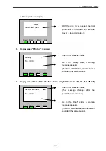
Страница 66: ...utlet Error The printer is in an error state Low Power Mode The printer is in Low Power Mode 1 Display when Ready is shown When the printer is in a normal state Display in the event of a warning Power Ready Error Data Ready Bad thermal head No 00000 Ready Power Ready Error Data No 00000 The printer status is shown The number of labels printed is shown The cumulative number of printed labels is sho...

Страница 67: ...Error Data Pause Head unit lifted Power Ready Error Data Pause No 00000 Power Ready Error Data The printer status is shown As in the Ready state a warning message appears The Error LED flashes and the buzzer sounds in the same manner With the Upper Unit lifted the number of printed labels is not shown until the Upper Unit is lowered completely With the Front Cover opened the number of printed labe...

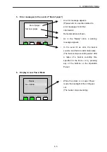
Страница 68: ...over open Power Ready Error Data The printer status is shown As in the Ready state a warning message appears The Error LED flashes and the buzzer sounds in the same manner With the Side Cover opened the total print count is not shown until the Side Cover is closed completely The printer status is shown The message changes after the peeled label is removed As in the Read state a warning message app...

Страница 69: ...d to error messages for further information Remedial action is shown While the printer is in Lower Power mode the backlight of the LCD goes out The buzzer stops sounding In the event of an error the buzzer sounds and the Error LED illuminates The buzzer stops sounding either after a lapse of a buzzer sounding time specified in the Menu or by pressing any of the buttons on the Operation Panel As in...

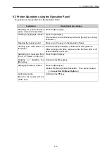
Страница 70: ...und Press any of the keys on the Operation Panel Clearing print data stored in the printer Hold down the Cancel key until the Data LED goes out After clearing print data make sure that the Data LED is off before initiating a print job Switching the message from Error to Pause on the LCD Press the Cancel key Enabling or disabling the Menu key Hold down the Menu key Displaying the Menu options Press...

Страница 71: ...ting whether to print the erroneous page again or not can be specified TOF After Booting Whether to perform the page alignment after power on or not can be specified Low Power Mode Whether to enable or disable Low Power Mode can be specified Lower Power min A time period until the printer goes into Low Power Mode can be specified Beep Volume A Beep Volume can be adjusted Beep Pattern A time period...

Страница 72: ...2 FPGA2 version Line 6 CPLD CPLD version Line 7 ODO Total running distance This value cannot be cleared Line 8 TRIP Running distance This value can be cleared Line 9 Cut Cut count Line 10 Lc Media length excluding a gap notch or black mark 1 Line 11 FL Media length including a gap notch or black mark 1 Line 12 Lo Sensor threshold value used to detect a gap notch or black mark from a label 1 Line 1...

Страница 73: ...r not is specified 1 If Yes is selected for Reprint Error Page in the Menu of the printer printing will be restarted from the erroneous page 2 If No is selected printing will be restarted from the page subsequent to the erroneous page Yes is selected in the as default Depending on print data or format an erroneous page may look like it has been printed completely Select No if any duplications are ...

Страница 74: ...pes shown on the LCD remain unchanged 4 No keys on the Operation Panel are pressed during the Low Power Mode transition time 5 No operations causing the printer to operate is exercised during the Low Power Mode transition time To return the printer to normal mode The printer returns from Low Power Mode to normal mode once any of the following conditions from 1 to 4 are satisfied No Conditions 1 Th...

Страница 75: ...options 10 seconds 60 seconds and Cont 10 seconds is selected as default 10 LCD Contrast The contrast of the LCD is specified It can be adjusted in 5 levels while the actual contrast is being checked The intermediate contrast level is selected as default 11 Language A language in which messages are shown on the LCD is selected There is a choice of 2 options Japanese and English English is selected...

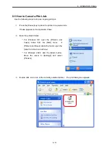
Страница 76: ...ars on the Operation Panel 2 Open the printers folder For Windows XP open the Printers and Faxes folder from the Start menu If Printers and Faxes cannot be found open the folder from the Control Panel For Windows 2000 click the Start button Move the cursor to Settings and select Printers 3 Double click on an icon of the currently selected printer The print dialog box appears ...

Страница 77: ...nter menu and delete all print jobs 5 The dialog box below appears asking if you want to cancel Click on the Yes button 6 Hold down the Cancel key on the Operation Panel until the Data LED goes out 7 Once the Data LED goes out look at the print dialog box and make sure that no print jobs remain in the print queue ...

Страница 78: ...ess the Menu key The Menu appears on the LCD 3 Select Test Print with the arrow keys 4 Press the Enter key 5 Select TTP with the arrow key 6 Press the Enter key and a print test will be initiated Select DTP when thermal paper is used for a print test Print test pattern is printed on 10 pieces of media in a row Press the Cancel key to stop it 9 2 Print Test Pattern ...

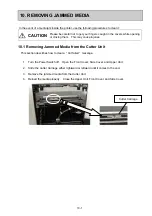
Страница 79: ...ause injuries 10 1 Removing Jammed Media from the Cutter Unit This section describes how to clear a Cut failed message 1 Turn the Power Switch off Open the Front Cover Side Cover and Upper Unit 2 Slide the Cutter Carriage either rightward or leftward until it comes to the end 3 Remove the jammed media from the Cutter Unit 4 Reload the media properly Close the Upper Unit Front Cover and Side Cover ...

Страница 80: ...ailed message 1 Press the Front Cover Unlock button and open the Front Cover 2 Remove the jammed media from the Peel off Unit 3 Reload the media properly Close the Front Cover Please refer to section 5 2 How to Load the Media for the Model with the Peel off Unit for media loading procedure Front Cover Unlock button Front Cover ...

Страница 81: ...tage and may cause an electric shock or injuries Do not use any cleaners using thinner benzene or flammable gas to clean the printer This may cause a fire Supplemental Remarks To maintain the printer performance and high quality printing for a long period of time clean the inside of the printer every 300 m of the printing distance which is equivalent to one roll of standard ribbon that is approxim...

Страница 82: ...er Side Cover and Upper Unit 3 Wipe the Reflective Media Sensor with a soft dry cloth to remove dirt or paper particles 4 Draw the Transmissive Media Edge Sensor frontward Wipe the opening of the Transmissive Media Edge Sensor to remove dirt or paper particles Transmissive Media Edge Sensor Opening Reflective Media Sensor ...

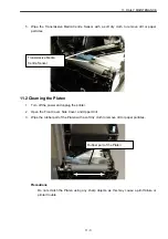
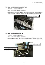
Страница 83: ...urn off the power and unplug the printer 2 Open the Front Cover Side Cover and Upper Unit 3 Wipe the rubber part of the Platen with a soft dry cloth to remove dirt or paper particles Precautions Do not scratch the Platen using any sharp objects as this may cause a print failure or printer trouble Rubber part of the Platen Transmissive Media Centre Sensor ...

Страница 84: ...n with a soft dry cloth Residues of the ribbon attached here can ribbon wrinkles 11 4 Cleaning the Ribbon Guide Bar 1 Turn off the power and unplug the printer 2 Open the Front Cover Side Cover and Upper Unit 3 Wipe the Ribbon Guide Bar black roller and the Ribbon Tensioner metal rod with a soft dry cloth to remove dirt Residues of the ribbon attached here can ribbon wrinkles Bottom of Ribbon Sepa...

Страница 85: ...ead 4 Wipe the Ribbon Guide Shaft metal rod clean with a soft dry cloth A dirty Ribbon Guide Shaft metal rod may cause ribbon wrinkles Precautions Do not scratch the Print Head element using any sharp objects as this may cause the print failure or a printer trouble Do not touch the heating element of the Print Head with bare hands as static electricity may damage the Print Head Ribbon Guide Shaft ...

Страница 86: ...Unit 1 Turn off the power and unplug the printer 2 Press the Front Cover Unlock button and open the Front Cover 3 Wipe the Rubber Roller black and the Pinch Roller white with a soft dry cloth to remove dirt 4 Wipe the Peel off Sensor clean with a soft dry cloth Precautions Do not scratch the rollers using any sharp objects as this may cause peeling off failures Peel off Sensor ...

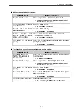
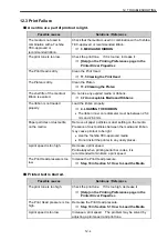
Страница 87: ...ower Switch is not turned on correctly Turn the Power Switch on indicates the power ON side 12 2 Problems while Printing Printing does not start Possible causes Solutions Reference READY is not shown on the Operation Panel If PAUSE is shown on the Operation Panel printing cannot be performed Ensure that the Front Cover and Side Cover are closed Press the Pause key and confirm that READY appears on...

Страница 88: ...Panel and start printing again 8 5 How to Cancel a Print Job Printing is performed but the media is not ejected successfully Possible causes Solutions Reference The media is not loaded properly Load the media properly Check the following points The media is placed between the Transmissive Media Edge Sensors 5 LOADING THE MEDIA The media is placed on the Reflective Media Sensor 5 LOADING THE MEDIA ...

Страница 89: ...t loaded properly Check that the ribbon is loaded when the thermal transfer printing is performed 4 LOADING THE RIBBON The loaded ribbon is torn or ejected with the media Possible causes Solutions Reference The loaded ribbon is not Toshiba TEC approved or recommended Check that the loaded ribbon is Toshiba TEC approved or recommended 3 MEDIA AND RIBBON The print tone is too high Check the print to...

Страница 90: ...on inner core diameter must be between 25 4 mm and 26 4 mm Paper particles or dust settle on the media Remove all paper particles or dust settling on the media Presence of dust particles between the media and ribbon may cause printout to be light Use the Toshiba TEC approved media Do not install the printer in any dusty places A print speed is too high Decrease a print speed Particularly when prin...

Страница 91: ...nly The ribbon is wider than the loaded media The printer is not installed in an appropriate operating environment Check the temperatures and humidity in the installation location of the printer 2 2 Installation Location The media is not loaded properly Adjust the Media Guide position so that they fit the media If there is clearance between the Media Guide and the media the media cannot be fed str...

Страница 92: ...o not use such media 3 MEDIA AND RIBBON The Platen is dirty Clean the Platen 11 2 Cleaning the Platen The media calibration is not performed properly If Easy or Strict feed mode is selected in the media settings in the printer driver perform a calibration again 7 4 Media Calibration Fixed Length feed mode is selected Select Easy or Strict feed mode in the printer driver to perform printing in acco...

Страница 93: ...ver settings If any wrong settings are found correct them Help on the Printing Preferences page in the Printer Driver Properties Check the following points The media size is specified correctly The print area is specified correctly The media calibration is not performed properly If Easy or Strict feed mode is selected in the printer driver perform the media calibration again 7 4 Media Calibration ...

Страница 94: ...e into the printer completely 2 5 Connecting the Printer to Your Computer Check that the LAN cable is also connected into a network device i e a hub properly The network settings on the print server are not made properly Please refer to the MPS1 contained in the supplied CD ROM for further information regarding the network settings on the print server The IP address assigned to the print server co...

Страница 95: ...correctly End of Paper The printer has run out of the media Load new media 5 LOADING THE MEDIA Side cover open The Side Cover is opened Close the Side Cover completely Head unit lifted The Upper Unit is lifted Push the Upper Unit downward by the Upper Unit Handle and lock it completely Paper info conflict The media calibration has failed Try the media calibration again 7 4 Media Calibration Check ...

Страница 96: ...ler in the Peel off Unit if it has worn out 1 5 2 Precaution when using the Peel off Unit Select and use an appropriate size of the media 3 MEDIA AND RIBBON Check the printer driver settings Help on the Printing Preferences page in the Printer Driver Properties The media size is specified correctly The print area is specified correctly 1 5 2 Precaution when using the Peel off Unit Cut failed The m...

Страница 97: ...nse can be returned to your host computer If no status is required to be obtained from the printer uncheck the Obtain printer information checkbox on the Device Settings tab in the printer driver In addition if no error messages are required to be displayed on your computer uncheck the Get error message checkbox on the Device Settings tab in the printer driver Overheated thermal head The thermal h...

Страница 98: ...igs or parts are available Q Can I use an ink ribbon narrower than a label I want to print an image only at the centre of a label So can I use a narrow ink ribbon for the cost saving purpose A Thermal transfer printing requires an ink ribbon Use an ink ribbon at least 10 mm wider than the backing paper of the loaded label If the loaded ink ribbon is narrower than the backing paper of the loaded la...

Страница 99: ...yout to place entire printed image within the guaranteed print area or decrease the print tone to prevent the ribbon from being torn apart Refer to section 3 5 Guaranteed Print Area for further information In addition refer to Help for the Printer Driver for further information regarding the changing of the print tone Please note that the warranty is not applied to any problems caused by printing ...

Страница 100: ...he model with the Peel off Unit Peeling was performed successfully before However these days the number of times that peeling fails has been increasing What should I do A The Rubber Roller in the Peel off Unit is a consumable It wears out from an extended period of use and becomes slicked As a result labels cannot be peeled off the backing paper As a guide the life of the Rubber Roller is a label ...

Страница 101: ...inter in order to avoid direct light Q I own the model with the Peel off Unit Can I operate the printer without using the Peel off Unit A You can use the model with the Peel off Unit without placing it in Strip mode However please note that there are some limitations on the printer operation Draw the loaded media and backing paper together over the Media Holding Roller in the Peel off Unit Draw th...

Страница 102: ...nd ribbons However when performing peel off operation the size of the available media is different Standard model Model with Peel off Unit Remarks Max backing paper width 120 mm Min label length 5 mm 12 mm Min media width 15 mm 10 mm Fanfold paper Perforation Allowed Not allowed Media may be torn off from perforation Min label thickness 0 05 mm 0 05 mm Max thickness of backing paper 0 1 mm 0 1 mm ...

Страница 103: ...ows 2000 Windows XP Windows Server 2003 Windows Vista Depth 455 mm Width 300 mm Dimension Height 353 5 mm including the rubber feet Weight 20 6 kg Input voltage 100 VAC to 240 VAC Frequency 50 60 Hz 48 to 62 Hz Rating Power consumption 250 W or less under normal operation Noise 75 dB or less Operating temperature range 5 to 40 C Print quality guaranteed at temperatures between 18 and 28 C Relative...

Страница 104: ...ueue name lp Control protocol HTTP Operating system Windows 2000 Windows XP Windows Server 2003 Windows Vista Depth 455 mm Width 300 mm Dimension Height 353 5 mm including the rubber feet Weight 21 0 kg Input voltage 100 VAC to 240 VAC Frequency 50 60 Hz 48 to 62 Hz Rating Power consumption 250 W or less under normal operation Noise 75 dB or less Operating temperature range 5 to 40 C Print quality...

Страница 105: ...dErrorState E Mail transmission capability SMTP Simple Mail Transfer Protocol Item Specifications SMTP Authentication feature SMTP authentication CRAM MD5 PLAIN LOGIN POP Before SMTP APOP supported No of e mail addresses that can be entered in the printer 2 E mail transmission interval Choice of options 1 to 10 000 minutes E mail priority 3 options Notice Error Emergency Errors that arise in the p...

Страница 106: ...rics or films is not allowed The Cutter Unit is a factory option 14 4 Peel off Unit Item Specifications Effective print speed 101 6 mm second or less same as a feed speed Peeling method Tensioning Peeling detection system A reflective photo sensor is used to detect a label Restrictions Peel off operation is not allowed when Perforated labels are used Fanfold labels are used Fabrics or films are us...

Страница 107: ...EMA U S A UL Finland FEI Norway NEMKO Europe HAR France UTE Spain AEE Power Cord Instruction 1 For use with 100 125 Vac mains power supply please select a power cord rated Min 125V 10A 2 For use with 200 240 Vac mains power supply please select a power cord rated Min 250V 3 Please select a power cord with the length of 4 5m or less Country Region North America Europe United Kingdom Australia Power...

Страница 108: ...rs can be disposed of with the product They will be separated at the recycling centers The black bar indicates that the product was placed on the market after August 13 2005 By ensuring this product is disposed of correctly you will help prevent potential negative consequences for the environmental and human health which could otherwise be caused by inappropriate waste handling of this product For...

Страница 109: ...E EO1 33085 ...

Отзывы: