background image


11.

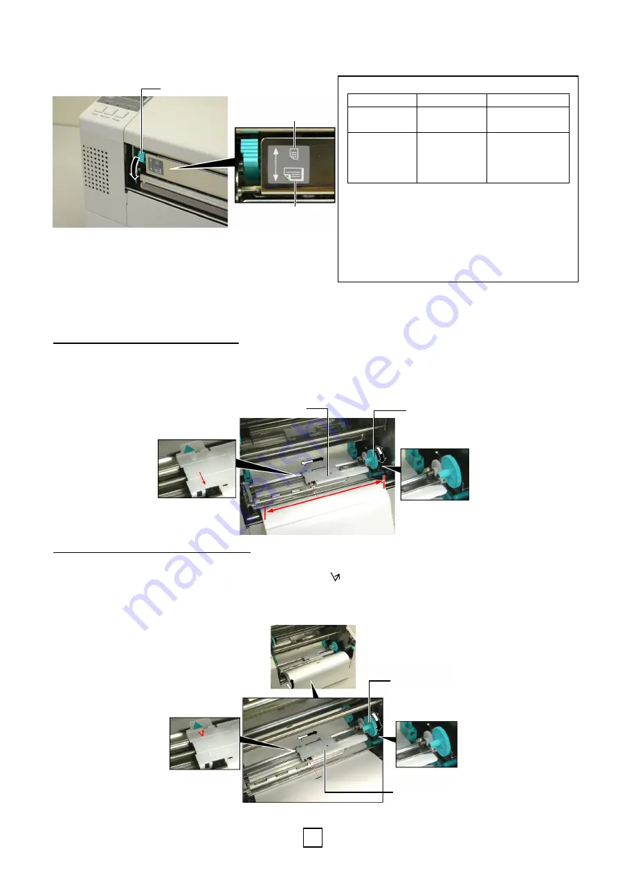
  If you are using labels or thick tag paper, then it may be necessary to increase the head pressure by lowering 

the Head Pressure Adjust Lever in the figure below. 


1.5  Setting Sensor Positions


After loading the media, as outlined in the previous paragraphs, it will usually be necessary to set the Media 
Sensors used to detect the print start position for label or tag printing.   

Feed Gap Sensor Position Adjustment 

1)

  With the Print Head Block raised, pass the labels under the Upper Sensor Ass’y as shown in the figure below. 

2)

  Rotate the Green Sensor Adjust Gear to move the Sensor Ass’y to the left or right to center the arrow ( 

 ) 

over the label. 

3)  With the sensor set to the center of the labels, it will be guaranteed to detect the gap between labels even if the 

labels are round. 


Black Mark Sensor Position Adjustment 

1)

  If the Black Mark is printed on the top of the tag media then simply rotate the Green Sensor Adjust Gear to 

move the Sensor Ass’y so that the Black Mark Indicator (    ) is directly in line with the Black Mark on the top 
of the paper. 

2)  If the Black Mark is printed on the bottom of the tag media then fold the media back to be able to see the 

Black Mark and its relationship to the Sensor Ass’y as shown in the figure below. 


Head Pressure Adjust Lever 

UP 

DOWN 

NOTE: Head Pressure Adjust Lever Position 

Lever position  Head pressure  Available media 

UP 

Low 

Thin tag paper  

Narrow media 

DOWN 

High 

Label  

Thick tag paper  

Wide media  

Full width media 


When using full width media, be sure to turn the Head 
Pressure Adjust Lever to DOWN, regardless of the 
thickness.


For all kinds of media except the full width media, 
turn the Head Pressure Adjust Lever to UP, if the 
print quality is to be ensured

.  


If the print tone is light when using thin tag paper, 
turn the Head Pressure Adjust Lever to DOWN.


Upper Sensor Ass’y

Green Sensor  
Adjust Gear 

Upper Sensor Ass’y 

Green Sensor Adjust Gear 

Содержание B-852 Series

Страница 1: ...losing the Top Cover 4 Be careful not to pinch your fingers by the Supply Holder Frame or Media Holders when loading the media AVERTISSEMENT 1 Ne touchez pas aux éléments en mouvement Pour éviter les risques que les doigts les bijoux les habits etc soient tirés vers les éléments en mouvement rassurez vous de charger le média lorsque l imprimante est arrêtée complètement 2 La tête chauffe beaucoup ...

Страница 2: ...le Supply Holder 3 Slide the Removable Supply Holder in the direction of arrow to remove it from the Supply Shaft 4 Rotate the green Supply Holder Locking Knob in the direction of arrow counterclockwise to loosen the Non removable Supply Holder 5 Slide the Non removable Supply Holder all the way to the end of the Supply Shaft until it stops Hook Hook NOTE After attaching the supply holder frame to...

Страница 3: ...de down after loading the media the media may drop by weight You might be injured by the dropped media AVERTISSEMENT Prenez garde à ne pas tenir le support de media avec la flasque amovible vers le bas car le rouleau de media peut tomber sous l effet de son proper poids Dans ce cas prenez garde à ne pas vous blesser lors de la chute WARNING CAUTION When installing the media roll do not push on the...

Страница 4: ...TION The reassembled Supply Holder Unit and media roll may be quite heavy so be careful not to pinch your fingers when installing the Supply Holder Unit onto the Supply Holder Frame ATTENTION Après remontage le support media et son media peuvent être assez lourds aussi faites attention à ne pas vous pincer les doigts lors de l installation NOTE Make sure that the brass bushings of the Supply Shaft...

Страница 5: ...or control purposes only It should be closed during normal operation AVERTISSEMENT Le capot supérieur peut être ouvert en fonctionnement à des fins de contrôle uniquement Il doit être fermé de façon habituelle WARNING CAUTION Be careful not touch the Print Head Element when raising the Print Head Block Failure to do this may cause missing dots by static electricity or other print quality problems ...

Страница 6: ...l it extends past the Platen until it extends past the cutter outlet when the optional cutter is attached 8 Grasp the right Paper Guide and move it to the left to close both Paper Guides and automatically center the media 9 Press the Paper Guide Locking Levers to lock the Paper Guides in place 10 After loading the media don t forget to move the Supply Holder Unit to the forward notch of the Supply...

Страница 7: ...printed on the top of the tag media then simply rotate the Green Sensor Adjust Gear to move the Sensor Ass y so that the Black Mark Indicator is directly in line with the Black Mark on the top of the paper 2 If the Black Mark is printed on the bottom of the tag media then fold the media back to be able to see the Black Mark and its relationship to the Sensor Ass y as shown in the figure below Head...

Страница 8: ...g Core to lock the Ribbon Supply Roll into position 1 The Print Head may become hot Do not touch the Print Head 2 The Top Cover can be opened during the operation for control purposes only It should be closed during normal operation 3 Risk of injuries Do not touch moving parts Disconnect the mains before maintenance of ribbon and media AVERTISSEMENT 1 Ne touchez pas la tête d impression car celle ...

Страница 9: ...80 Brussels 7 Repeat steps 4 through 6 with the Ribbon Take up Roll locking it in place also 8 Take up any slack in the ribbon by rotating the green Core Winding Gear on the take up in the direction of arrow 9 Close the Print Head Block and lock it in place by pressing at locations and in the figure below NOTE Be sure to remove any slack in the ribbon Printing with a wrinkled ribbon will lower the...

Отзывы: